MAX Operation & Service Manual 103MAX Operation & Service Manual Section 6: Maintenance & Service 103
HOW TO REPLACE, ADJUST, OR LUBRICATE PARTS
The Bufng and Squeegee Systems
Using the Buffer Brush Adjustment Tool
The MAX is equipped with its own adjustment tool for measuring the height of the buffer brush. The
adjustment tool is mounted inside the lane machine between the electronic enclosure and the center
compartment wall separating the cleaning section from the center compartment. It is fastened by two
wing nuts. Refer to
Figure6-8.
The adjustment tool has three notches used to verify adjustments. The buffer brush may use all three
notches (1/16”, 1/8”, and 3/16”). The buffer brush is set at 1/16” at the factory. To properly use the
Buffer Brush adjustment tool, position so it spans the rear shaft wheel and the traction drive wheel on
one side of the machine and then the opposite side. The notches should align with the buffer brush so
they are spanning the assembly. Refer to
Figure6-8.
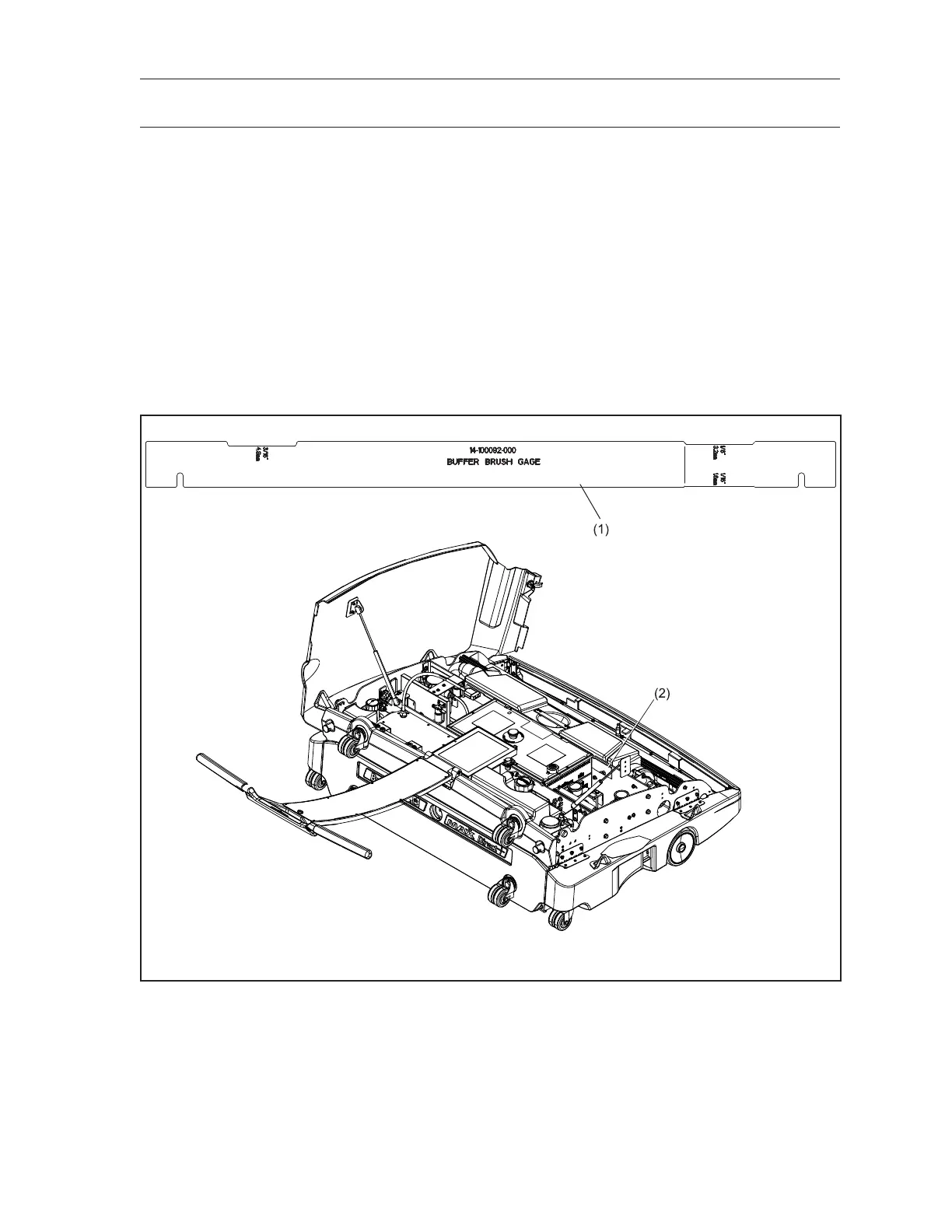
Figure6-8.AdjustmentToolStorageLocation
(1) SQUEEGEE/BUFFER ADJUSTMENT
TOOL
(2) ADJUSTMENT TOOL STORAGE
LOCATION