MAX Operation & Service Manual 131MAX Operation & Service Manual Section 6: Maintenance & Service 131
Replacing the Buffer Brush
Tools needed: 1/8” Allen wrench, and long 1/4” T-Wrench (supplied with kit).
Parts needed: Buffer Brush Assembly, part number 14-100043-000, and attachment screw, part number
11-005308-000, blue loctite.
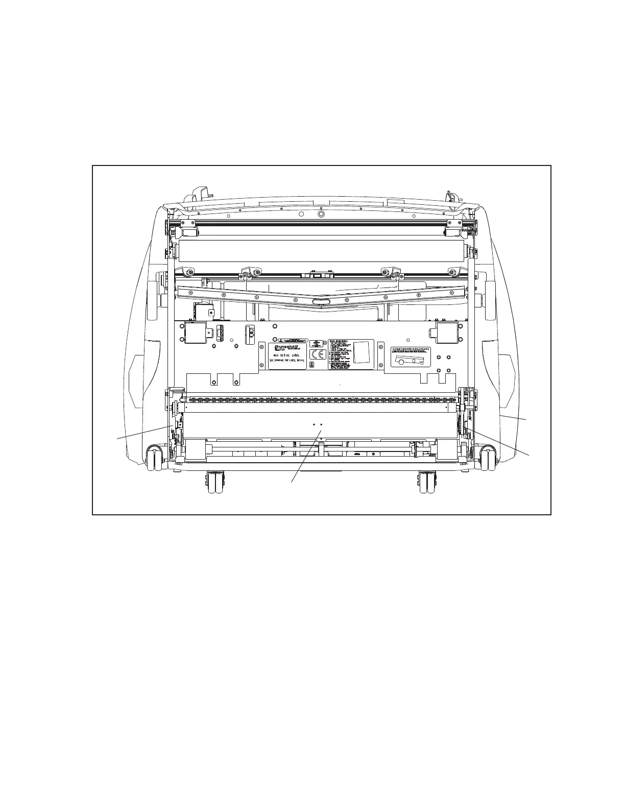
Refer to Figure6-21.
(1)
(2)
(3)
(4)
Figure6-21.ReplacingtheBufferBrush
(1) WALL MOUNTED BEARING
(2) BUFFER BRUSH
(3) BUFFER DRIVE PULLEY (4) ACCESS HOLE FOR 1/4” SOCKET
HEAD CAP SCREW
1. Place machine in transport position.
2. Remove the 10-pin side cover by removing the 3 pins that mount the cover to the machine
frame.
3. Remove 2 set screws on the 10-pin side, wall-mounted buffer brush bearing using a 1/8” Allen
wrench.
4. Remove socket-head cap screw inside the buffer drive pulley using 1/4” T-wrench. This will
allow the buffer brush shaft to separate from the buffer drive pulley, which will remain in the
machine.