VPLS for an MPLS-based Provider Core
VPLS is a multipoint Layer 2 VPN technology that connects two or more customer devices using bridging
techniques. A bridge domain, which is the building block for multipoint bridging, is present on each of the
PE routers. The access connections to the bridge domain on a PE router are called attachment circuits. The
attachment circuits can be a set of physical ports, virtual ports, or both that are connected to the bridge at each
PE device in the network.
After provisioning attachment circuits, neighbor relationships across the MPLS network for this specific
instance are established through a set of manual commands identifying the end PEs. When the neighbor
association is complete, a full mesh of pseudowires is established among the network-facing provider edge
devices, which is a gateway between the MPLS core and the customer domain.
The MPLS/IP provider core simulates a virtual bridge that connects the multiple attachment circuits on each
of the PE devices together to form a single broadcast domain. This also requires all of the PE routers that are
participating in a VPLS instance to form emulated virtual circuits (VCs) among them.
Now, the service provider network starts switching the packets within the bridged domain specific to the
customer by looking at destination MAC addresses. All traffic with unknown, broadcast, and multicast
destination MAC addresses is flooded to all the connected customer edge devices, which connect to the service
provider network. The network-facing provider edge devices learn the source MAC addresses as the packets
are flooded. The traffic is unicasted to the customer edge device for all the learned MAC addresses.
In the MPLS provider core, the VPLS pseudowire traffic can be dynamically routed over any interface that
supports LDP protocol.
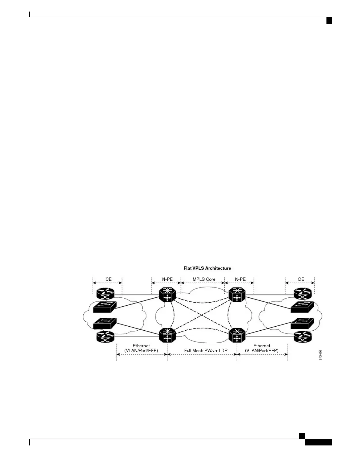
VPLS Architecture
The basic or flat VPLS architecture allows for the end-to-end connection between the provider edge (PE)
routers to provide multipoint ethernet services. Following figure shows a flat VPLS architecture illustrating
the interconnection between the network provider edge (N-PE) nodes over an IP/MPLS network.
Figure 18: Basic VPLS Architecture
The VPLS network requires the creation of a Bridge Domain (Layer 2 broadcast domain) on each of the PE
routers. The VPLS provider edge device holds all the VPLS forwarding MAC tables and bridge domain
information. In addition, it is responsible for all flooding broadcast frames and multicast replications.
The PEs in the VPLS architecture are connected with a full mesh of Pseudowires (PWs). A Virtual Forwarding
Instance (VFI) is used to interconnect the mesh of pseudowires. A bridge domain is connected to a VFI to
L2VPN and Ethernet Services Configuration Guide for Cisco ASR 9000 Series Routers, IOS XR Release 6.3.x
207
Implementing Multipoint Layer 2 Services
VPLS for an MPLS-based Provider Core

 Loading...


