Virtual Ethernet Segment (vES)
Traditionally, multi-homing access to EVPN bridge is through bundle Ethernet connection or a physical
Ethernet connection. The Virtual Ethernet Segment (vES) allows a Customer Edge (CE) to access EVPN
bridge through MPLS network. The logical connection between CE and EVPN provider edge (PE) is a
pseudowire (PW). Using vES you can connect VxLAN EVPN-based data center and a legacy data center
through PW based virtual circuit.
The VxLAN EVPN-based data centers and legacy data centers are interconnected through access pseudowire
(PW), access virtual forwarding instance (VFI), or both. One vES is created for each access PW and one vES
is created per access VFI. This feature supports only single-active mode.
Use access VFI for connecting multiple sites in a mesh topology. Use access PW for connecting few sites in
hub and spoke topology.
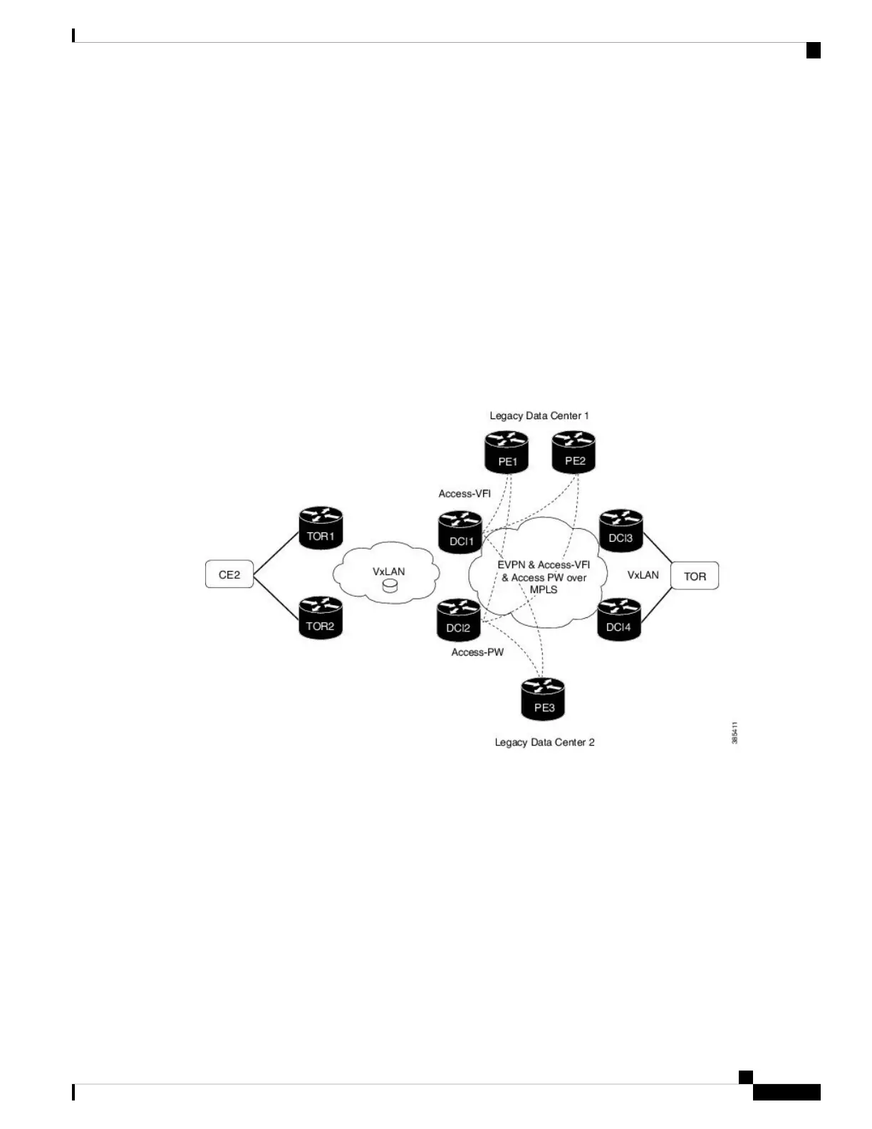
Figure 80: Virtual Ethernet Segment (vES)
Consider the topology where EVPN data centers are connected to legacy data centers through access PW or
access VFI on a single Ethernet segment, which is vES.
Consider a traffic flow from CE2 to PE3. CE2 sends the traffic to DCI1 or DCI2 through EVPN VxLAN.
DCI1 and DCI2 are connected to PE3 through access PW on a single Ethernet segment. DCI1 and DCI2
advertise Type 4 routes, and then do designated forwarder (DF) election. The non-DF blocks the traffic on
that particular Ethernet segment. Both DCI1 and DCI2 can do the DF election. DCI1 and DCI2 perform DF
election after they discover each other. Either one of them can be a DF and other a non-DF. The traffic is
forwarded through the DF. The non-DF path is in stand-by mode. DF election is used to prevent traffic loop.
DCI1 or DCI2 sends the traffic to PE3.
Consider a traffic flow from CE2 to PE1 and PE2. CE2 sends the traffic to DCI1 or DCI2 through EVPN
VxLAN. DCI1 and DCI2 are connected to PE1 and PE2 through access VFI. DCI1 and DCI2 are connected
to PE1 and PE2 through access VFI on a single Ethernet segment. DCI1 or DCI2 sends the traffic to PE1 and
PE2. DCI1 and DCI2 advertise Type 4 routes, and then do designated forwarder (DF) election. The non-DF
L2VPN and Ethernet Services Configuration Guide for Cisco ASR 9000 Series Routers, IOS XR Release 6.3.x
541
EVPN Features
Virtual Ethernet Segment (vES)

 Loading...


