l2vpn
xconnect group examples
p2p r2-connect
interface GigabitEthernet0/5/0/1.1
interface GigabitEthernet0/5/0/2.1
!
!
!
Protocol traffic enters router R1 at the GigabitEthernet subinterface 0/1/0/1.1. Router R1 detects the frames
as protocol frames, and performs L2PT encapsulation at the customer facing interface. Inside R1, the local
connection r1-connect connects R1's customer-facing and service provider-facing interfaces. The traffic then
flows out of router R1 on GigabitEthernet subinterface 0/1/0/2.1 through several other service provider network
routers or switches (switch cloud) into router R2 at GigabitEthernet subinterface 0/5/0/1.1. Router R2 connects
the customer-facing and service provider-facing interfaces through a local connection r2-connect. Therefore,
traffic is sent to the customer-facing interface GigabitEthernet 0/5/0/2.1. At this interface, an L2PT decapsulation
occurs and the protocol traffic flows out of router R2 into the customer network.
Without L2PT being configured the customer protocol frames that are sent into R1 are terminated. The customer
traffic can consist of a variety of traffic; the protocol frames comprise a small percentage of the overall traffic
stream.
L2PT in the Reverse Mode with Protocol Frame Tagging
The Cisco ASR 9000 Series Routers can perform L2PT encapsulation and decapsulation on supported L2
protocol frames that have VLAN headers. The L2 protocol frames do not have VLAN headers. However, in
a service provider (SP) network that transports customer protocol traffic from one customer campus to another,
this capability can be put to use within the SP network.
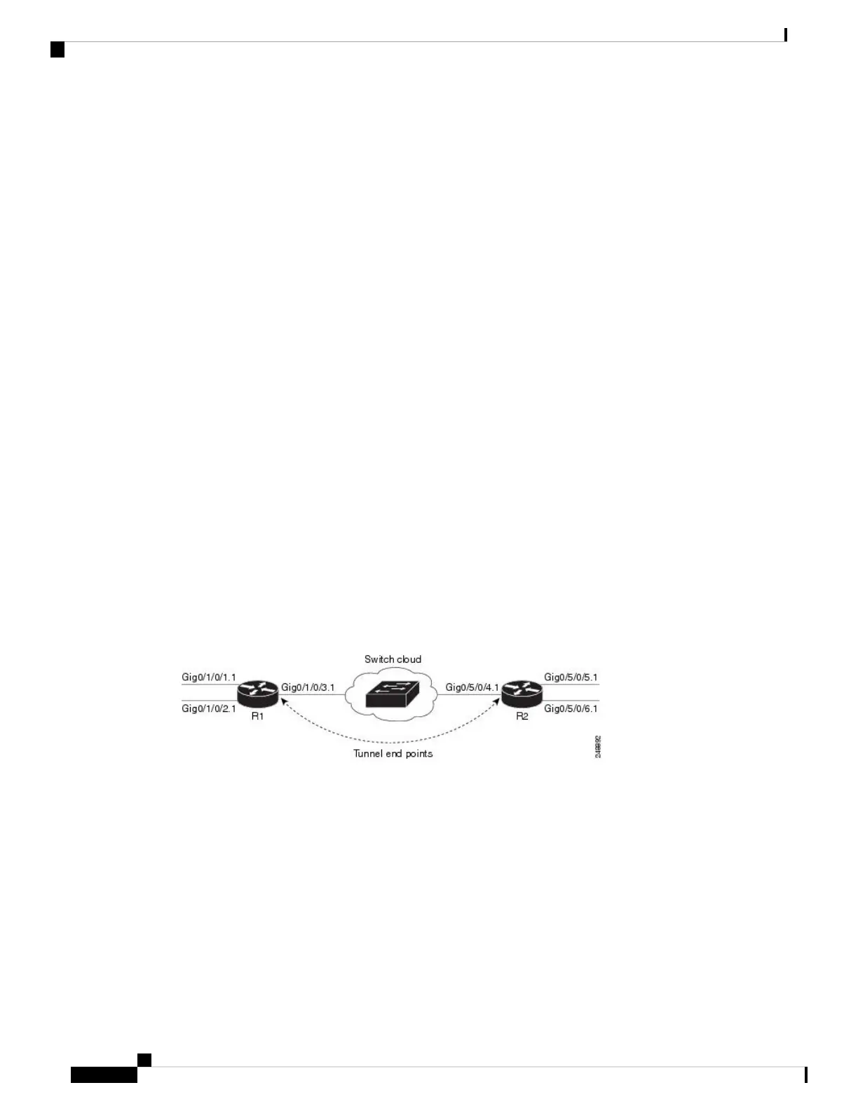
Figure below shows L2PT configured in the reverse mode. Assume that the customer traffic that enters R1 is
trunked, that is all traffic is tagged. The only untagged traffic is the protocol traffic, that comes from the
customer network.
Figure 5: L2PT in reverse mode
When L2PT is configured in the reverse mode, the L2PT encapsulation occurs when the frame exits the
interface. Likewise, in reverse mode decapsulation is performed when the frame enters the interface. Therefore,
the L2PT tunnel is formed between the service provider-facing interfaces, instead of the customer-facing
interfaces.
In this example, once the protocol traffic enters router R1, a VLAN tag is added to it. Before the traffic is sent
through the service provider network, a second VLAN tag is added (100). The Cisco ASR 9000 Series Routers
perform the L2PT encapsulation on a double-tagged protocol frame.
The above figure above shows four customer-facing interfaces (R1: GigabitEthernet subinterface 0/1/0.1.1,
GigabitEthernet subinterface 0/1/0/2.1 and R2: GigabitEthernet subinterface 0/5/0/5.1, GigabitEthernet
subinterface 0/5/0/6.1) and two service provider-facing interfaces (R1: GigabitEthernet subinterface 0/1/0/3.1
and R2: GigabitEthernet subinterface 0/5/0/4.1).
L2VPN and Ethernet Services Configuration Guide for Cisco ASR 9000 Series Routers, IOS XR Release 6.3.x
42
Ethernet Features
L2PT in the Reverse Mode with Protocol Frame Tagging

 Loading...


