• show spanning-tree mstag mst-name bpdu interface interface-name
• show spanning-tree mstag mst-name topology-change flushes
Analogous commands are available for REPAG.
MSTAG Uplink Tracking
The MSTAG Uplink Tracking feature monitors the connectivity of an nPE gateway device to the core or
aggregation network. This feature prevents traffic loss if there is a connectivity failure between a gateway
router and the core network. This feature also ensures reduction in the frequency of traffic outages and reduced
need for redundancy in connectivity from the gateway to the core network.
Multiple Spanning Tree Access Gateway (MSTAG) tracks the connectivity of interfaces that face the core.
When an nPE device loses connectivity to the core, it sends start-up BPDUs indicating that all core-facing
interfaces are down. This allows the access ring to switch the traffic to go through the other nPE device.
The core connectivity is based on a per-protocol instance. This is because each access ring corresponds to an
access ring, and they may use different interfaces to forward traffic to the core. Therefore, it is possible for
different protocol instances to have different core connectivity status.
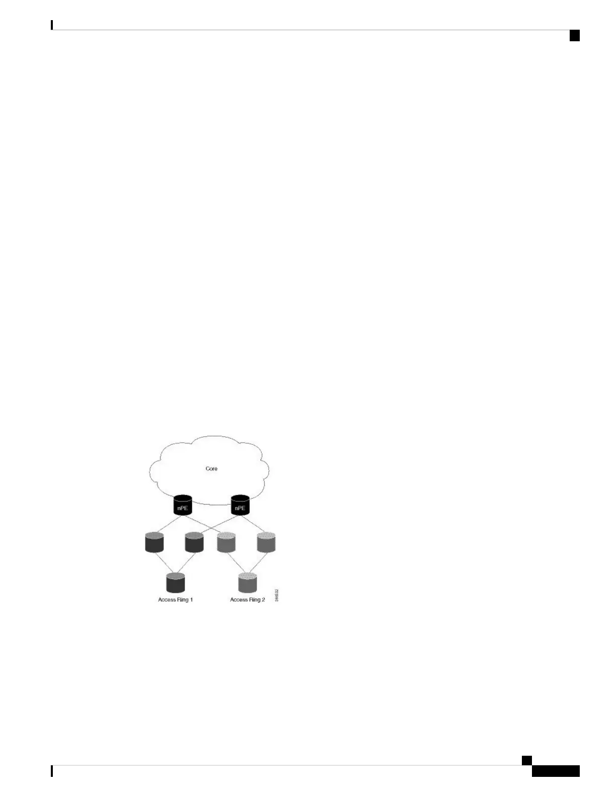
In this topology there are two access rings. Each one is connected to the core through a pair of nPE devices
in which MSTAG is configured. MSTAG allows each access ring to run the STP independently. When one
of the nPE devices lose core connectivity, it starts sending start-up BPDUs indicating that traffic must flow
through the other side of the access ring. Once core connectivity is available, the nPE device starts sending
the standard BPDUs. If pre-empt delay is set, it continues to send the start-up BPDUs until the timer expires.
For example, if pre-empt delay is configured as ten seconds, the nPE device sends startup BPDUs for the first
ten seconds after core connectivity becomes available. After ten seconds, it starts sending standard BPDUs.
Figure 62: MSTAG Uplink Tracking
Core Connectivity Failure
The following diagram illustrates how the nPE device sends start-up BPDUs when it loses core connectivity.
L2VPN and Ethernet Services Configuration Guide for Cisco ASR 9000 Series Routers, IOS XR Release 6.3.x
439
Implementing Multiple Spanning Tree Protocol
MSTAG Uplink Tracking

 Loading...


