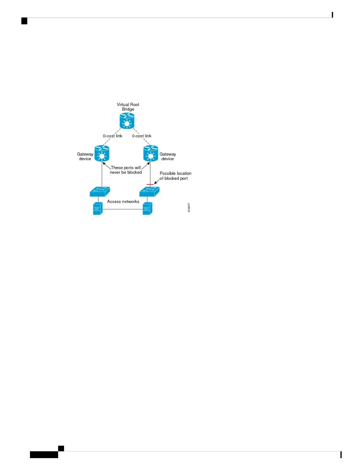
With these assumptions, an STP topology can be envisaged where for every spanning tree, there is a virtual
root bridge behind (that is, on the core side of) the gateway devices, and both gateway devices have a zero
cost path to the virtual root bridge. In this case, the ports that connect the gateway devices to the access network
would never be blocked by the spanning tree protocol, but would always be in the forwarding state. This is
illustrated in the following figure.
Figure 58: Access Network
With this topology, it can be observed that the BPDUs sent by the gateway devices are constant: since the
root bridge never changes (as we assume the aggregation or core network always provides connectivity) and
the ports are always forwarding, the information sent in the BPDUs never changes.
Access gateway makes use of this by removing the need to run the full STP protocol and associated state
machines on the gateway devices, and instead just sends statically configured BPDUs towards the access
network. The BPDUs are configured so as to mimic the behavior above, so that they contain the same
information that would be sent if the full protocol was running. To the access devices, it appears that the
gateway devices are fully participating in the protocol; however, since in fact the gateway devices are just
sending static BPDUs, very little memory or CPU resource is needed on the gateway devices, and many access
networks can be supported simultaneously.
For the most part, the gateway devices can ignore any BPDUs received from the access network; however,
one exception is when the access network signals a topology change. The gateway devices can act on this
appropriately, for example by triggering an LDP MAC withdrawal in the case where the core or aggregation
network uses VPLS.
In many cases, it is not necessary to have direct connectivity between the gateway devices; since the gateway
devices statically send configured BPDUs over the access links, they can each be configured independently
(so long as the configuration on each is consistent). This also means that different access networks can use
different pairs of gateway devices, as shown in the following figure.
L2VPN and Ethernet Services Configuration Guide for Cisco ASR 9000 Series Routers, IOS XR Release 6.3.x
420
Implementing Multiple Spanning Tree Protocol
Overview of Access Gateway

 Loading...


