NOTE: If any of the following parameters are enabled, the Data
Flow Control DAD/DPD Driver starts at Byte 1 (second byte) of
the Fieldbus Master Input Area, and Byte 0 (first byte) is reserved
for these Digital Input Line Echo parameters.
If none of the following parameters are enabled, the Data Flow
Control DAD/DPD Driver starts at Byte 0 (first byte) of the
Fieldbus Master Input Area.
For more details, refer to the DAD/DPD Driver Reference Manual.
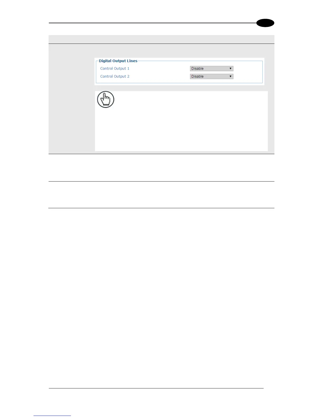
This parameter is configurable only if Digital Output 1 Use is set to
Profibus/Profinet. Select Disable or Enable from the drop-down list. If enabled, it
allows the Fieldbus Master to drive the Scanner Master or SC5000 Controller
Output 1 via bit 0 in Byte 0 (first byte) of the Output Area.
This parameter is configurable only if Digital Output 2 Use is set to
Profibus/Profinet. Select Disable or Enable from the drop-down list. If enabled, it
allows the Fieldbus Master to drive the Scanner Master or SC5000 Controller
Output 2 via bit 1 in Byte 0 (first byte) of the Output Area.
3. When you have finished making changes, click Update All to save all pending changes,
click Reset All to revert to all previously saved values, and click Reset Page to revert to
previous saved values on the current page.