This is a read-only parameter. It displays the address of one of the Profinet
channels to be used for Host communication.
This is a read-only parameter. The bus rate is set to Auto allowing the Host to
manage the bus speed.
Static: the IP Address can be set manually through the IP Address, IP Net Mask
and IP Gateway parameters.
DHCP: the IP address is assigned by a DHCP server. In this case the IP Address
parameters are read-only and display the DHCP assigned address.
Remote: the IP Address is assigned by a remote network device (PC) using an
IPConfig address configuration application. In this case the IP address parameters
are read-only and display the remotely assigned address.
Enter the device Internet Protocol (IP) network address in the field provided.
Consult your network administrator to obtain a new address.
Enter the device subnet mask address in the field provided. Consult your network
administrator to obtain a new address.
Enter the device gateway address in the field provided. Consult your network
administrator to obtain a new address.
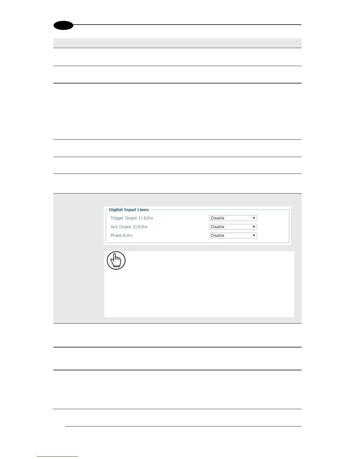
NOTE: If any of the following parameters are enabled, the Data
Flow Control DAD/DPD Driver starts at Byte 1 (second byte) of
the Fieldbus Master Input Area, and Byte 0 (first byte) is reserved
for these Digital Input Line Echo parameters.
If none of the following parameters are enabled, the Data Flow
Control DAD/DPD Driver starts at Byte 0 (first byte) of the
Fieldbus Master Input Area.
For more details, refer to the DAD/DPD Driver Reference Manual.
Select Disable or Enable from the drop-down list. If enabled, the Scanner Master
or SC5000 Controller Trigger (Input 1) status is echoed to the Fieldbus Master
via bit 0 in Byte 0 (first byte) of the Input Area.
Select Disable or Enable from the drop-down list. If enabled, the Scanner Master
or SC5000 Controller Input 3 status is echoed to the Fieldbus Master via bit 2 in
Byte 0 (first byte) of the Input Area.
This parameter is configurable only if Start Input from Bus is enabled.
Select Disable or Enable from the drop-down list. If enabled, the Reading Phase
status is echoed to the Fieldbus Master via bit 7 in Byte 0 (first byte) of the Input
Area.