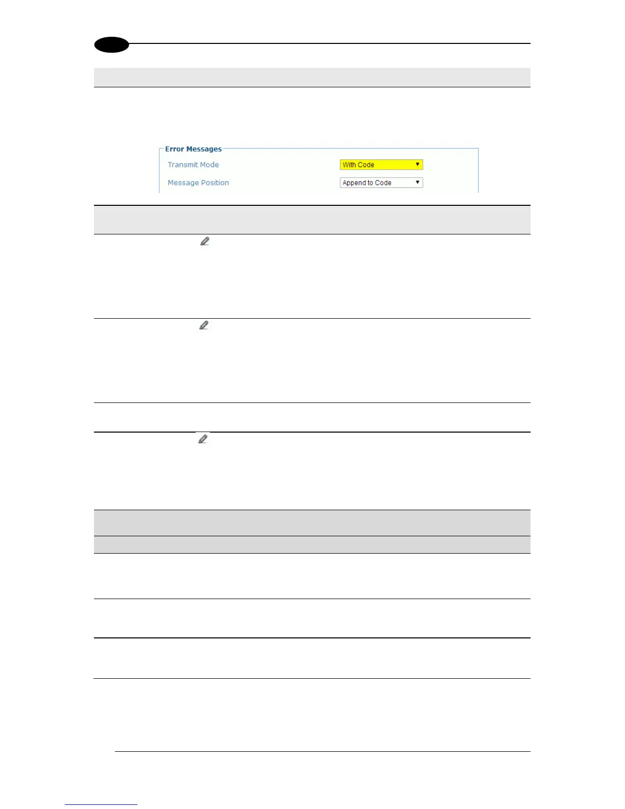
Select Append to Code or Replace Code from the drop-down list. If Transmit Mode is
synchronous (With Code), the diagnostic messages will be transmitted on the same
interface used for code transmission. This selection determines if the messages will
replace the code or be appended to it.
Click to activate the Text Entry Tool to define the header string (up to 128
characters) as a block preceding the diagnostic message. Use characters from NUL
(00H) to ~ (7EH).
Click Submit to save your text to the origin window text field, or click Cancel to return
to origin window without transferring text.
Click to activate the Text Entry Tool to define the terminator string (up to 128
characters) as a block following the diagnostic message. Use characters from NUL
(00H) to ~ (7EH).
Click Submit to save your text to the origin window text field, or click Cancel to return
to origin window without transferring text.
Select Numeric or Global String from the drop-down list to define how the message
will be sent.
Global String
(max. 32 chars)
Click to activate the Text Entry Tool to define the Global String message (up to
32 bytes) that will be sent as a diagnostic message for any detected diagnostic
error.
Click Submit to save your text to the origin window text field, or click Cancel to return
to origin window without transferring text.
Select the check box next to the destination(s) to be used for the diagnostic
messages.
PackTrack
Debug Message
Enable
Select the checkbox to enable debug messages for PackTrack. If selected, this
parameter allows transmitting messages concerning the system functioning.
PackTrack
Debug Message
Port
Select Main Serial, Aux Serial, or Socket n from the drop-down list. The debug
message will be transmitted through the selected port.
PackTrack
Debug Message
Digital Input
Select None, Trigger (Input 1), Aux (Input 3), or I/O 4 (Input 4) from the drop-down
list. This selection defines which digital input will be used to trigger debug message
transmission.
3. When you have finished making changes, click Update All to save all pending changes,
click Reset All to revert to all previously saved values, and click Reset Page to revert to
previous saved values on the current page.