3 Devices
DVP-20PM Application Manual
3-64
Setting value Response speed
4 32 ms
3 108 ms
2 256 ms
1 or 0 500 ms
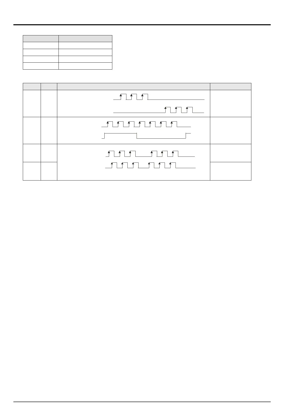
3. Bit 8 and bit 9 in D1864 (D1944, D2024): Setting the input pulses generated by the manual pulse
generator specified
b9 b8 Input type (positive logic) Description
0 0
FP Clockwise pulses
RP Counterclockwise pulses
Counting up/down
0 1
FP Pulses
RP Directions
Counterclockwise
Clockwise
Pulses+Directions
1 0 A/B-phase pulses
1 1
Counterclockwise
Clockwise
FP A-phase pulses
RP B-phase pulses
Four times the
frequency of
A/B-phase pulses
3.12.2 Introduction of Modes of Motion
1. There are ten modes of motions.
1. Returning home 6. Two-speed motion
2. JOG motion 7. Inserting two-speed motion
3. Single-speed motion 8. Variable motion
4. Inserting single-speed motion 9. Manual pulse generator mode
5. Triggering single-speed motion by means of an
external signal*
10. Starting a cyclic/noncyclic electronic cam*
2. If more than one mode of motion is activated, they will be executed in particular order.
1. Stopping the motion of the axis specified by
software
7. Single-speed motion
2. Returning home 8. Inserting single-speed motion
3. Positive JOG motion
9. Triggering single-speed motion by means of an
external signal*
4. Negative JOG motion 10. Two-speed motion
5. Manual pulse generator mode 11. Inserting two-speed motion
6. Variable motion 12. Starting a cyclic/noncyclic electronic cam*
*: Only DVP-20PM series motion controllers support this mode of motion.
If a mode of motion is activated when another mode of motion is executed, the DVP-20PM series
motion controller will continue executing the original mode.