5 Applied Instructions and Basic Usage
EndofProfile
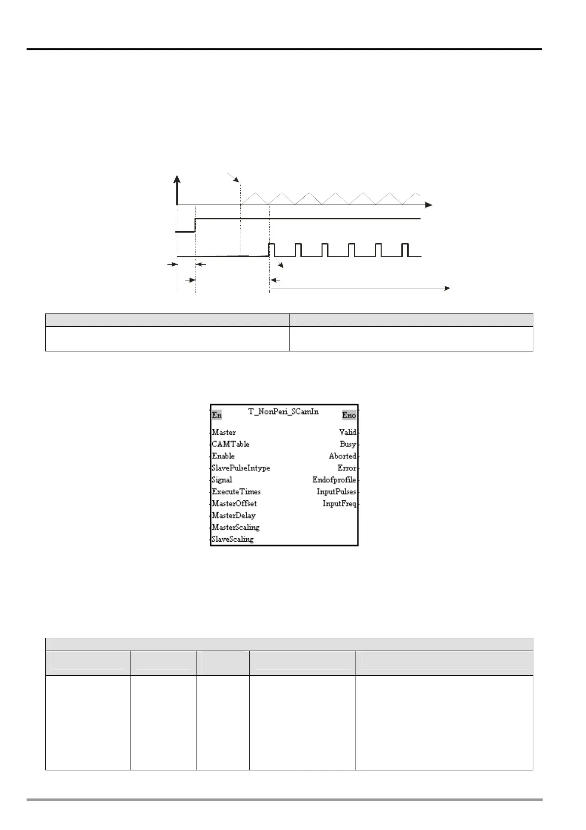
The steps of starting a cyclic electronic cam are as follows.
At the time T1, the Enable input pin is set to True (a uniaxial cyclic electronic cam is started).
After the time T2 elapses, the EndOfProfile output pin will be set to True. The value of the
EndOfProfile output pin will be cleared after one scan cycle.
During the time T3, the EndOfProfile output pin is set to True when an electronic cam cycle is
complete, and the value of the EndOfProfile output pin will be cleared after one scan cycle.
Starting
Enable input pin)
a cyclic
electronic cam
(
A cam cycle is complete.
EndOfProfile output pin)(
T1
T2
T3
Start
Cleared automatically
Position of
the master axis
Displacement of
the slav e axis
3. Troubleshooting
Error Troubleshooting
The values of input pins in the motion control function
block are incorrect.
Check whether the values of the input pins are in the
ranges allowed.
4. Modules which are supported
The motion control function block T_Peri_SCamIn supports DVP20PM00D and DVP20PM00M.
5.10.20 Uniaxial Noncyclic Electronic Cam Motion
1. Motion control function block
The motion control function block T_NonPeri_SCamIn is used to start electronic cam motion. The value
of the Master input pin indicates a master axis. The first axis is used as a slave axis. The motion of the
slave axis specified follows the motion of the master axis specified. The value of the MasterOffset input
pin indicates the starting angle of the master axis specified. The value of the MasterDelay input pin
indicates the number of pulses the master axis specified sends before electronic cam motion is started.
2. Input pins/Output pins
Input pin
Name Function
Data
type
Setting value Time when a value is valid
Master
Master axis
number
WORD
K1: A0± and B0±
K2: FP± for the Y-axis
(No external wiring is
needed.)
K3: FP± and RP± for
the Y-axis
(No
external wiring is
needed.)
The value of the Master input pin is
valid when there is a transition in the
Enable input pin’s signal from low to
high.
DVP-20PM Application Manual
5-202