12 High-speed Comparison and High-speed Capture
DVP-20PM Application Manual
12-3
Item Bit Setting value DVP-20PM series motion controller
14 STOP1 for the Y-axis
External
trigger
[15-12]
15 START1 for the Y-axis
12.2 High-speed Comparison
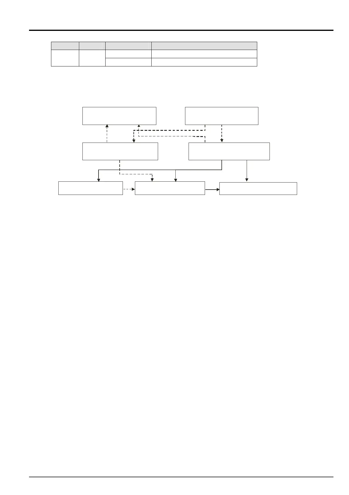
A high-speed comparison is shown below. Users use FROM/TO to read/write values so that they can
compare data.
(B)FROM K253 K1 D0 D50 (A)TO K253 K1 D0 D50
(D)Data register n (n=0~7) (C) Control register n (n=0~7)
(E) Comparison source
(F) Comparison condition
(G) Output terminal/Counter
※
The dotted lines are data procedures, and the solid lines are control procedures.
Block (A): The instruction TO is used to write data into control registers (block C) and data registers
(block D).
Block (B): The instruction FROM is used to read data from control registers (block C) and data registers
(block D).
Block (C): User set a comparison source (block E), a comparison condition (block F), and an output
terminal (block G) in a control register in accordance with the value it receives by means of
TO.
Block (D): The value that users write into data registers by means of the instruction TO is compared
with a comparison source (block E).
Block (E): The present positions of three axes, the values in C200 and C204 are comparison sources.
Block (F): There are three comparison conditions, they are equal to, greater than or equal to, and less
than or equal to. If block D and block E meet the comparison condition set, the output
terminal selected will be set to ON, the counter selected will be reset, the output terminal
selected will be reset to OFF, or the counter selected will not be reset.
Block (G): If a comparison condition is met, CLR0±, CLR1±, Y2, Y3, C200, or C204 will be set or reset.
Procedure for a high-speed comparison: The instruction TO is used to write data into control registers
and data registers (block A).The comparison source set (block E) is compared with the value in data
registers (block D). The comparison result meets the condition set (block F).CLR0±, CLR1±, Y2, Y3,
C200, or C204 will be set or reset (block G).
Example
【
Description】
The high-speed counter C204 is used. If the value in C204 is greater than 100, Y1 will be set to ON.
If the value in C204 is greater than 300, Y1 will be reset to OFF. Two comparators are used in a
program. One comparator is used to set Y1 to ON, and the other is used to reset Y1 to OFF. When
Y1 is set to ON, no LED indicator on the DVP-20PM series motion controller used will indicate that
Y1 is ON, but users can know whether Y1 is ON by means of its external wiring. As a result, the
terminal C1 is connected to the terminal 24G, Y1 is connected to X7, S/S2 is connected to +24V. A
manual pulse generator is used, and is connected to A1± and B1±.