5 Applied Instructions and Basic Usage
or
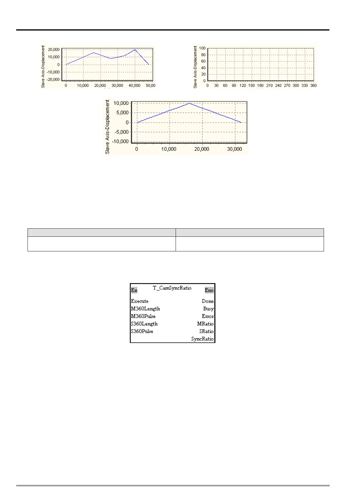
(a) Original cam chart
(b) Three pairs of coordinates in a cam chart
Set M80 to True. The pair of coordinates (16000, 10000) is written into cam point number 1.
Set M81 to True. The pair of coordinates (32000, 0) is written into cam point number 2.
Set M82 to True. The pair of coordinates (0, 0) is written into cam point number 3.
Set M83 to True. Cam point number 1 and cam point number 2 are read. Check whether the values
read are the same as the values written into cam point number 1 and cam point number 2.
After cam chart 0 is modified, the chart displayed will be composed of the coordinates written into
cam chart 0.
4. Troubleshooting
Error Troubleshooting
The values of input pins in the motion control function
block are incorrect.
Check whether the values of the input pins are in the
ranges allowed.
5. Modules which are supported
The motion control function block T_CamWrite supports DVP20PM00D and DVP20PM00M.
5.10.24 Calculating a Synchronization Ratio
1. Motion control function block
The motion control function block T_CamSyncRatio is used to calculate a synchronization ratio. A
synchronization ration is calculated by means of the M360Length input pin, the M360Pulse input pin,
the S360Length input pin, and the S360Pulse input pin. (The value of the M360Length input pin
indicates physical quantity, and the value of the M360Pulse input pin indicates the number of pulses.
The value of the S360Length input pin indicates physical quantity, and the value of the S360Pulse input
pin indicates the number of pulses.)
DVP-20PM Application Manual
5-214