9 Electronic Cam
9.2 Operation of an Electronic Cam
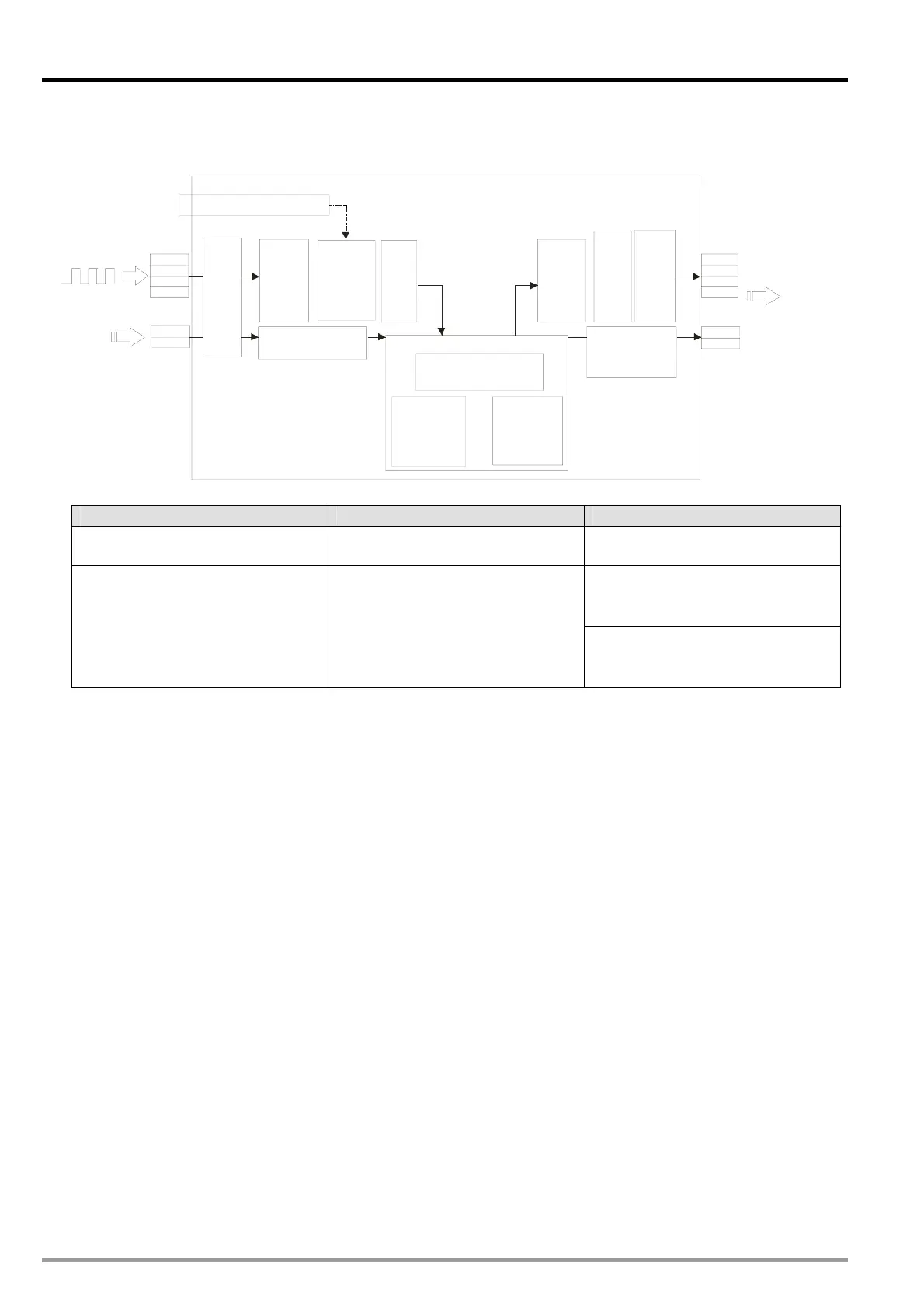
Structure
(1)
(2)
(3)
(3)
(4)
(6)
(7)
(8)
(9)
(4)
or
Sending a
synchronization
signal
Starting a virtual axis
DVP-20PM series motion controller
MPGA0+
MPGA0-
MPGB0+
MPGB0-
START0
PG0
FP0+
FP0-
RP0+
RP0-
CLR0
CLR1
START0/PG0
Cam data
(Resolution: 10~2048)
Output
Starting a
cyclic
electronic
cam
Setting an
input pulse
type
Pulses sent
by a master
cam
Pulses sent by
a master axis
Setting an
output pulse
type
Pulses sent
by a slave
cam
Setting terminals
Input ratio
Output ratio
Starting a
noncyclic
electronic
cam
Starting a noncyclic
electronic cam
Steps
Step 1 Step 2 Step 3
Initial setting Setting a master axis
Starting/Stopping an electronic
cam
(7) Starting/Stopping a cam which
operates cyclically
(1) Creating electronic cam data
(2) Setting terminals
(3) Setting an input/output pulse
type
(4) Setting an input/output ratio
Setting a starting angle
Servo encode for the master axis
specified
Pulse signals sent by the master
axis specified
(6) Starting a virtual axis
(8) Starting/Stopping a cam which
does not operate cyclically
9.2.1 Initial Setting
9.2.1.1 Creating Electronic Cam Data
There are two methods of creating electronic cam data.
Method 1: Use DTO instruction to create electronic cam data directly
Method 2: Use the electronic cam chart in PMSoft to draw the cam curve
Please refer to section 9.4 for more information.
9.2.1.2 Setting Terminals
Input terminals
1. MPGA0/MPGB0: Pulse input terminal for Master. Max allowable frequency: 200 kHz
2. START0/PG0: Input terminal for enabling noncyclic electronic cam
Output terminals
1. FP/RP: Output terminal for pulse output of electronic cam. Max output frequency: 500 kHz
2. CLR0/CLR1: Output terminal for electronic cam synchronized output signal. When D1839,
D1838 (PI) CP≦ (Current Position) of Master (X axis) D1843,≦ D1842 (PII), CLR0/CLR1 will
be ON. (For special application of CLR0/CLR1, please refer to section 9.3.)
DVP-20PM Application Manual
9-2