11 CANopen Communication Card
6. The users have to set the IP address of DVP- FPMC in the Communication Parameter
section.
7. After the users select the link name created in step 5 in the Input window for an element, they
can operate the memory defined by the element by means of Ethernet.
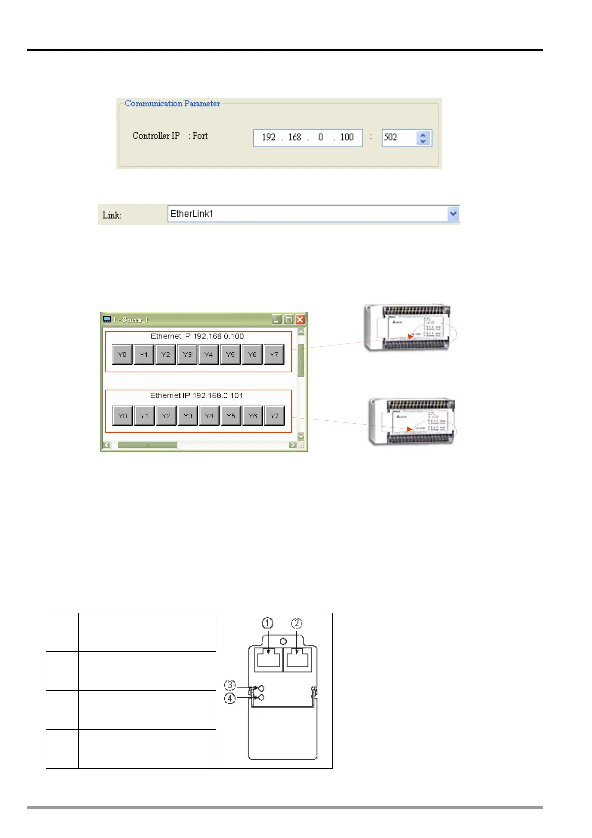
The HMI needs to control Y0~Y7 on two DVP-10PM series motion controllers which function as
slaves. The interface required is shown below. The buttons Y0~Y7 correspond to Y0~Y7 on
EtherLink1 and EtherLink2, that is to say, they correspond to Y0~Y7 on the two slaves connected.
After the setting described above is completed, the HMI can connect to the two slaves by means of
Ethernet.
IP: 192.168.0.100
IP: 192.168.0.10
11.7.2 Communication between DVP-FPMC and PMSoft
Before users create communication between DVP-FPMC
and PMSoft, they have to use COMMG to
create an Ethernet driver. An Ethernet driver can be used to upload the program in a DVP-10PM series
motion controller, download a program into a DVP-20PM series motion controller, and monitor a
DVP-20PM series motion controller.
Wiring hardware
Users can connect the network port on DVP-FPMC to a network port on a PC by means of a
network cable. If DVP-FPMC is connected to a PC, the Ethernet LED indicator on DVP-FPMC will
be ON. Please check the setting of hardware and or the setting of the PC is the Ethernet LED
indicator is not ON.
CANopen port
Ethernet port
CANopen LED indicator
Ethernet LED indicator
DVP-20PM Application Manual
11-24

 Loading...


