9 Electronic Cam
9.4.2.5 Offset Comp
ensation for a Slave Error
In field application, errors occur between the actual output position on device and the target output
position on electronic cam curve. In addition, the error could be larger as the increase of execution
times. Aiming at this problem users need to apply offset compensation according to the error value
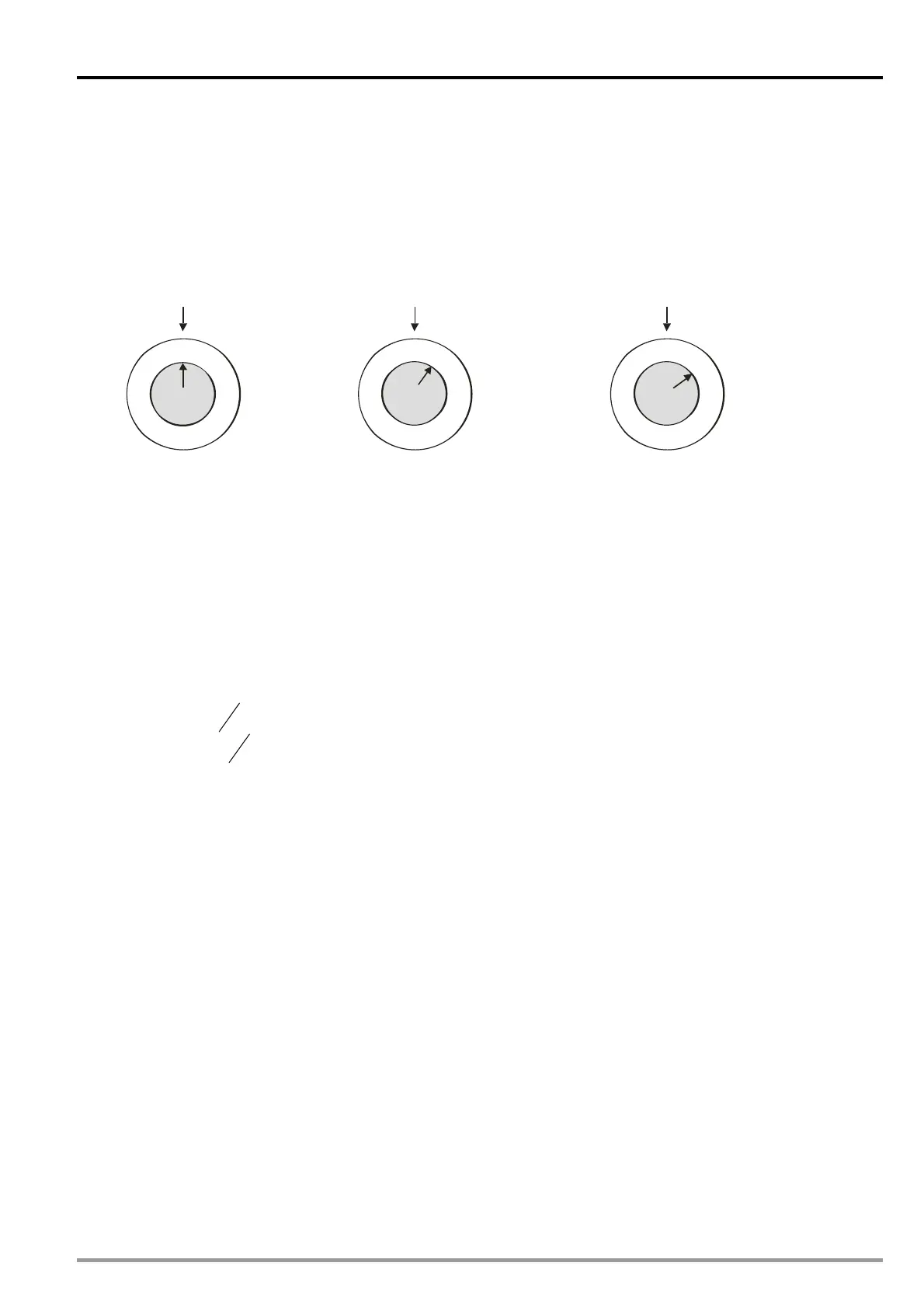
between DOG signal and the end point of Slave position (D108). First, backup the initial value of D108
(Figure A). Second, compare the value in backup register (D128) with D108, which has errors to the
initial value (Figure B and Figure C). Third, take the difference between the 2 registers as the reference
value for offset compensation.
Dog
D108=0
Dog
D108=100
Dog
D108=200
(A)
(B)
(C)
End point of
Slave position
End point of
Slave position
End point of
Slave position
Application method:
1. Read initial Slave error. The initial error is the value obtained by subtracting the captured value at
DOG with the captured value at electronic cam completion.
2. When the Slave error increases in the next cycle, subtract the increased Slave error with the initial
Slave error, and users can have the real Slave error.
3. Subtract Length per round of Slave, which is one of the electronic cam parameter, with the real
Slave error and users can have the real error between the results of electronic cam output and the
device output. When the real error is between “± half of Slave length”, or when the real error
exceeds “± half of Slave length”, users conduct offset compensation for the error.
4. Compensation
ratio OffsetSlave of lengtherror RealOffsetSlave of length error Real
ratio OffsetSlave of lengtherror RealOffsetSlave of length error Real
)(
2
1
)-(
2
1
5. In the next cycle, input the modified length of Slave (with offset) by DTO instruction and the offset
compensation is completed.
Example
【Function】
The example is used for judging if real error between DOG switch and electronic cam completion
exists. When error occurs, calculate offset value for compensation on the length of Slave. In this
case, D302 refers to the modified length of Slave.
【Steps】
1. Run the program and read the electronic cam status by DFROM instruction. Read the data in
CR#10001 of special module K100 to D100~D108.
2. Set M3 to write the length of Slave into D126 and the initial Slave error into D128. Calculate the
real error, i.e. difference between the increased error and the initial error, and take the half of
Slave length as the reference.
3. Real error>1/2 length of Slave→Offset=(Real error-Length of Slave)×Offset ratio
4. Real error<1/2 length of Slave→Offset=(Real error+Length of Slave)×Offset ratio
5. Set M4 to calculate the modified length of Slave with offset compensation.
6. When M4 is reset, fill the original length of Slave back to D302.
DVP-20PM Application Manual
9-45

 Loading...