9 Electronic Cam
9.6.3.1 Operati
on of a Flying Shear
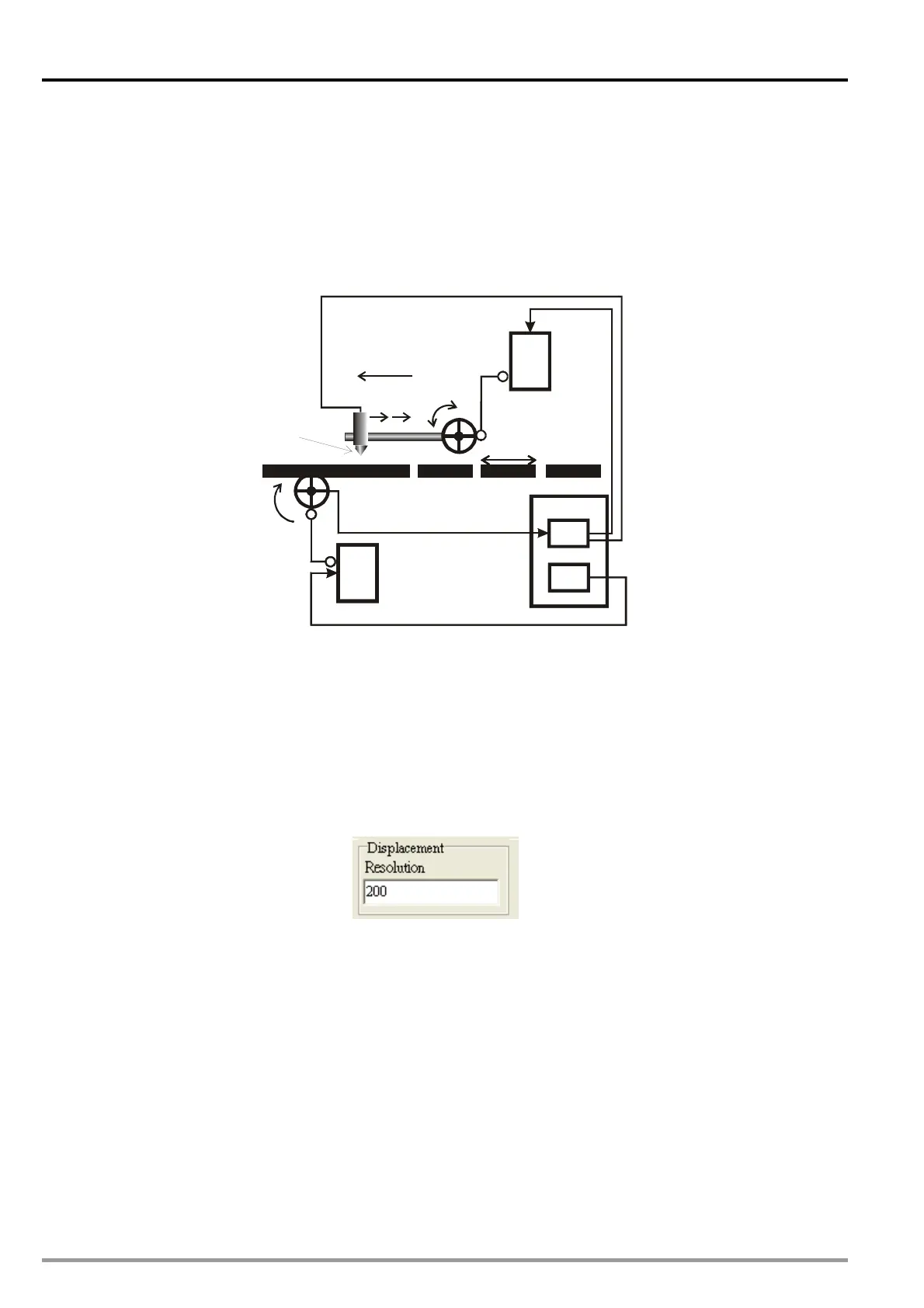
The operation and simple wiring of flying shear is illustrated as below. Positions 1, 2, 3 and 4
respectively indicate starting position, sync-start position, sync-end position and ready position. When
Master (Y axis) executes, Slave (X axis) accelerates from position 1 to position 2, reaching the
synchronizing speed. The sync speed is maintained from position 2 to position 3. After position3, Slave
decelerates in reverse direction and returns to position 4 (Same as position 1). The cycle repeats for
continuous flying shear operation.
SERVO
SERVO
20PM
CAM
X axis
Y axis
Jog
Encoder output
Cut Length
SERVO
CAM
Jog
Cut Length
SERVO
20PM
CAM
X axis
Y axis
Jog
Encoder output
Cut Length
SERVO
CAM
Jog
Cut Length
123
SyncOut
blade
4
9.6.3.2 Creating an Electronic Cam Curve
In electronic cam design process, PMSoft creates electronic cam data by operating displacement data
to generate the velocity data and the acc data. However, in this case users need to control the velocity
between Slave and Master. To obtain the velocity, users can input the velocity data in the displacement
table for creating the velocity curve. After the velocity curve is created with displacement and acc curve,
export the velocity data by clicking “Export” and import the velocity data by clicking “Import Speed Data”,
so that the velocity relationship between Slave and Master can be obtained.
1. Set the max resolution as 200.
DVP-20PM Application Manual
9-60

 Loading...


