2 Hardware Specifications and Wiring
DVP-20PM Application Manual
2-1
2.1 Hardware Specifications
Electrical specifications and wiring are described in this chapter. Please refer to chapter 5~chapter 6 for
more information about the writing of a program and the use of instructions. For more information about the
peripherals purchased, please refer to the manuals attached to them.
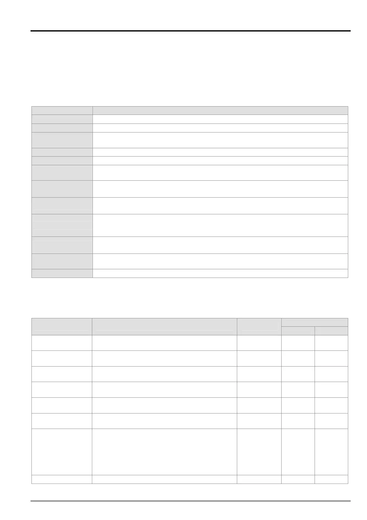
2.1.1 Specifications for Power
Item 20PM
Supply voltage
100~240 V AC (-15%~10%), 50/60 Hz5%
Fuse
2 A/250 V AC
Power
Consumption
60 V A
24 V DC power
500 mA
Power protection
24 V DC output is equipped with a short circuit protection.
Surge voltage
withstand level
1500 V AC (Primary-secondary), 1500 V AC (Primary-PE), 500 V AC (Secondary-PE)
Insulation
impedance
Above 5 MΩ
(The voltage between all input terminals/output terminals and the ground is 500 V DC.)
Noise immunity
ESD: 8 kV air discharge
EFT: Power line: 2 kV; digital I/O: 1 kV; analog & communication I/O: 250 V
Ground
The diameter of the ground should not be less than the diameters of the cables connected
to the terminals L and N. (If several DVP-20PM series motion controllers are used, please
use single-point ground.)
Operation/Storage
Operation:0°C~55°C (Temperature), 5~95% (Humidity), pollution degree 2
Storage: -25°C ~70°C (Temperature), 5~95% (Humidity)
Vibration/Shock
resistance
International standards IEC 61131-2, IEC 68-2-6 (TEST Fc)/IEC 61131-2 & IEC 68-2-27
(TEST Ea)
Weight
Approximately 478/688 g
2.1.2 Electrical Specifications for Input Terminals/Output Terminals
Electrical specifications for input terminals:
DVP20PM00D
Maximum input
Terminal Description Response
Current Voltage
START0 and
START1
Input terminals for starting DVP20PM00D 10 ms 6 mA 24 V
STOP0 and
STOP1
Input terminals for stopping DVP20PM00D 10 ms 6 mA 24 V
LSP0/LSN0 and
LSP1/LSN1
Positive limit switches/Left limit switches (for the
X-axis and the Y-axis)
10 ms 6 mA 24 V
A0+, A0-, A1+,
and A1-
A-phase input terminals for manual pulse
generators (differential input terminals)
200 kHz 15 mA 5~24 V
B0+, B0-, B1+,
and B1-
B-phase input terminals for manual pulse
generators (differential input terminals)
200 kHz 15 mA 5~24 V
PG0+, PG0-,
PG1+, and PG1-
PG signals (differential input terminals) 200 kHz 15 mA 5~24 V
DOG0 and DOG1
The use of the input terminals varies with the
mode used.
1. DOG signals for returning home
2. Signals for starting the insertion of
single-speed motion or the insertion of
two-speed motion
1 ms 6 mA 24 V
X0~X7 General input terminals 200 kHz 15 mA 24 V