10 Application of G-codes
DVP-20PM Application Manual
10-17
The program in O100 is as figure (B).
es of three axes are set.
N, the data in OX0 is loaded into CAM chart-0.
he data source is in CAM chart-0)
s
corresponding CAM chart, and only G00, G01, G04 and
Step 1: When M1 is ON, the work mod
a. D1847=H1000
b.
D1927=H1000
c. D2007=H1000
Step 2: When M2 is O
a. When the value in D1868 is H400, Ox0 is selected.
b. Load the data in OX0 into CAM chart-0.
Step 3: When M7 is ON, Ox0 is executed. (T
a. When the value in D1868 is H4000, cam chart 0 is selected.
b. Enable cyclic electronic cam.
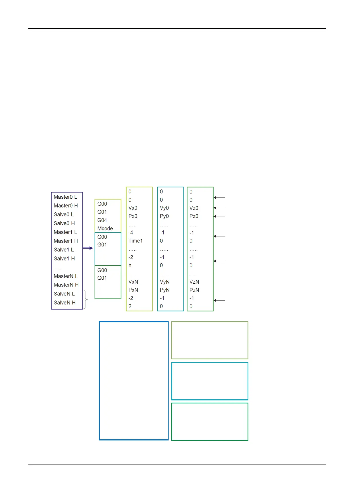
10.4 Storing G-codes/M-code
In this function, data in OXn is loaded to the
M-codes applied in “With mode” are supported for this function. The below diagram explains the data
allocation in CAM chart.
Arrangement of CAM data (16-bit)
(X-axis)
(X-axis)
(Y-axis)
(Y-axis)
(Z-axis)
(Z-axis)
32-bit
floating-point
value
X-axis
Y-axis
Z-axis
Start of an Ox motion subroutine
Velocity: G0. G1
Displacement
G04
Mn
M02 (End of the Ox motion subroutine)
Arrangement of data after the reading of the data (16-bit)
0
499
Start0=0
n0=500
CAM chart
X-axis
Y-axis
Z-axis
500
999
Start1=2000
n1=500
1000
1499
Start2=4000
n2=500
Resolution
n=1500