10 Application of G-codes
DVP-20PM Application Manual
10-18
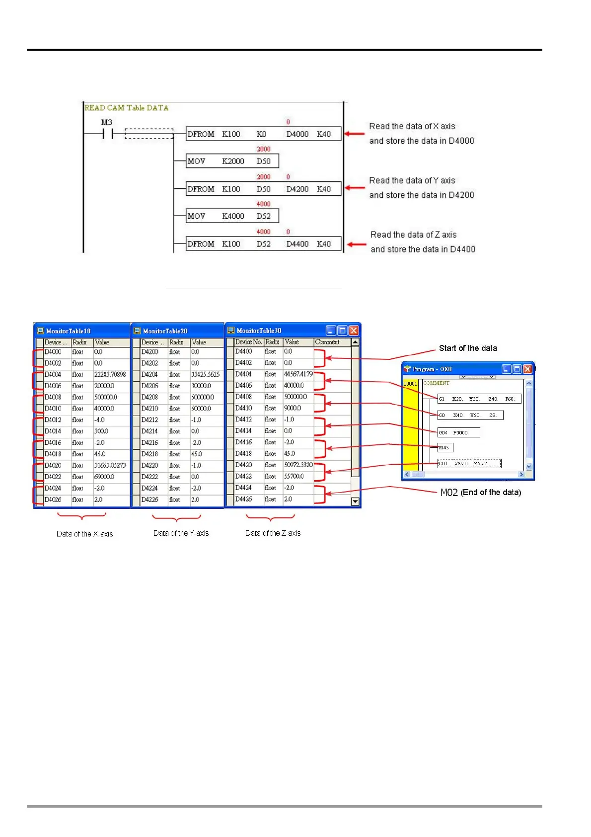
he example program uses CAM chart-0 with max resolution 1500. The below program are applied for T
reading the data of 3 axes in CAM chart.
P.S.: Note: In the instruction DFROM (DTO) K100 K0 D4000 K40, K100 indicates access in CAM
chart-0. If K101 is set, it indicates access in CAM chart-1. If K102 is set, it indicates access in
CAM chart-2.
Conclusions drawn from the data above:
he lower data is position. “-1” will be set if the speed data is not
d data is fixed as 500K. The lower data is position. “-1” will be set if the speed data is not
0/G01: Write -1 into the speed data of G00/G01 on specific axis, and the instruction on
a indicates G04. The lower data is pause time. Unit: 10ms.
aced in all axes.
1. The first data of each axis is 0.
2. G01: The upper data is speed; t
specified.
3. G00: Spee
specified.
4. Stopping G0
the axis will be stopped.
5. G04: The value -4 in upper dat
6. M-code: The value -2 indicates an M-code. The lower data is an M-code number.
7. End of the data: -2 and 2 indicates M02, which is the end of the CAM data.
8. G04 can only be placed in X axis.
9. An M-code instruction should be pl

 Loading...


