6 Basic Usage of Motion Instructions and G-codes
6.3 Descriptions of Motion Instructions
Applicable model
Motion
instruction
number
20PM
00
DRV
P
1
FX V
1
P
2
FY V
2
Z P
3
FZ V
3
Rapid positioning
Word device Double word device
K H D KK HH DD
P
1
V
1
P
2
V
2
P
3
V
3
Note: The instruction supports devices.
The devices supported can be
modified by V devices can Z
devices. Please refer to the
specifications for the DVP-20PM
series motion controller used for
more information about the device
ranges available. The instruction can
be followed by an M-code
instruction.
Explanation
P
1
: Target position of the X-axis; V
1
: Speed at which the X-axis moves; P
2
: Target
position of the Y-axis; V
2
: Speed at which the Y-axis moves; P
3
: Target position of
the Z-axis; V
3
: Speed at which the Z-axis moves
Maximum V
1
, V
2
, V
3
= V
MAX
Range of parameters: (16-bit) K=-32,768~32,767; H=0~FFFF; D=0~9,999;
(32-bit) KK=-2,147,483,648~2,147,483,647; HH=0~FFFFFFFF; DD=0~9,998
Acceleration/deceleration time and bias speed can be set in special data
registers.
Acceleration/deceleration time increases or decreases in proportional to the
setting of V
MAX
.
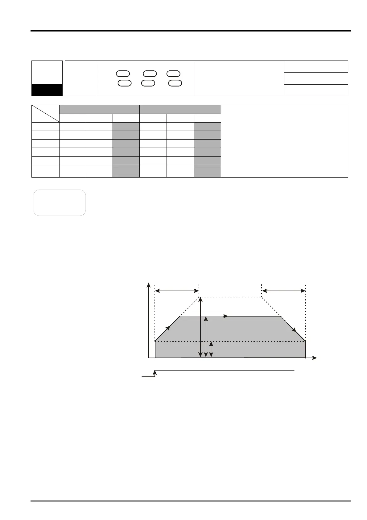
Timing diagram
Speed
T
ACC
DEC
V
MAX
Time
V
BIAS
Start
Operation speed
Target position
16-bit devices and 32-bit devices can be used together.
If users set the moving speed on an axis, they have to set the target position on
the axis. However, if they set the target position, it is not a must to set the moving
speed.
DVP-20PM Application Manual
6-7

 Loading...


