11 CANopen Communication Card
11.6 Setting a DVP-FPMC Mode
A2 mode
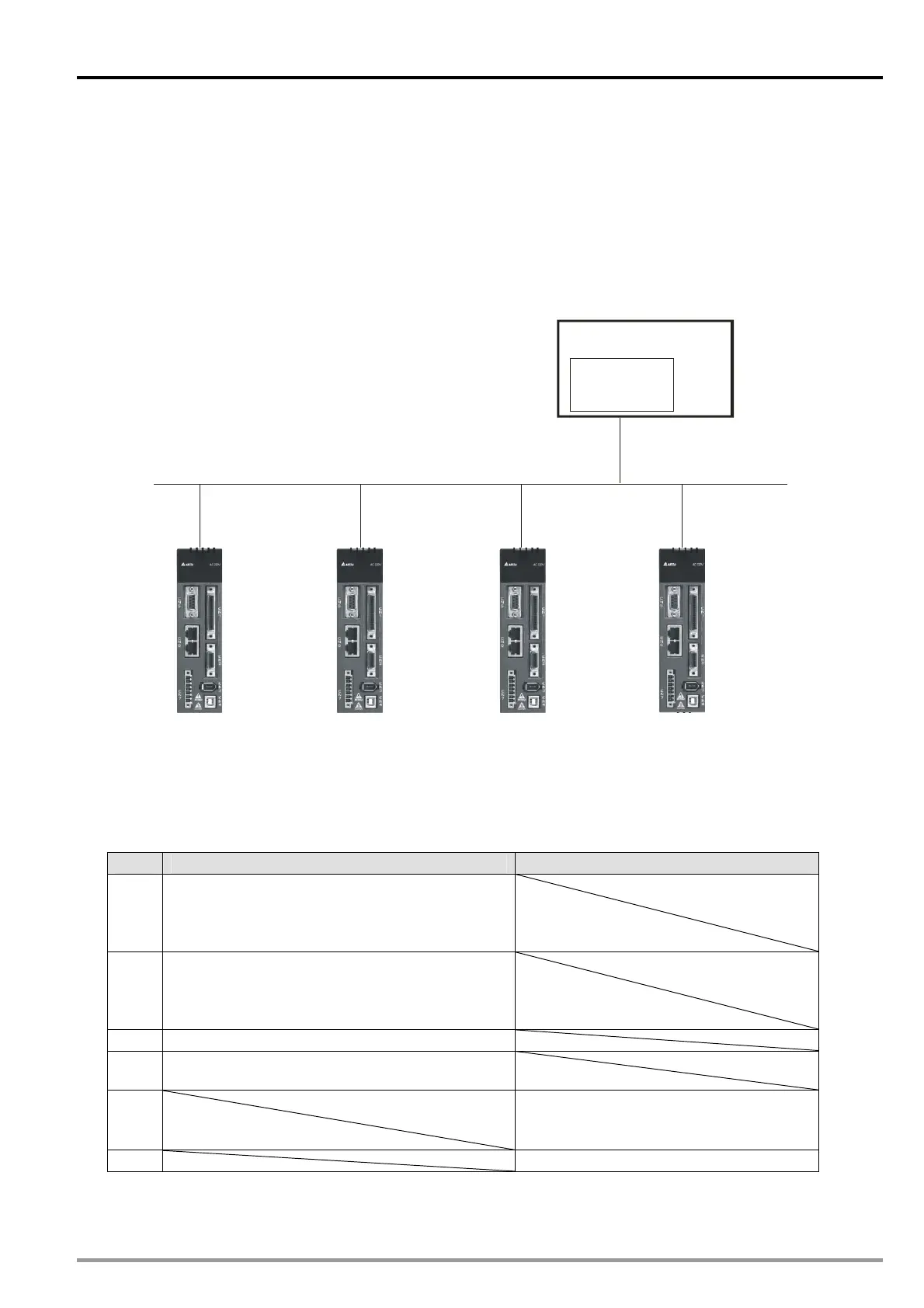
In an A2 mode, DVP-FPMC communicates with four Delta ASDA-A2 series servo drives through a
CANopen network. During the communication, DVP-FPMC functions as a master, and the servo
drives functions as slaves. The communication structure required is show below. The default node
ID of DVP-FPMC is 127. The objects which are connected are node ID 1~ node ID 4. After users
assign node ID 1~node ID4 to the servo drives, the servo drives can exchange data with
DVP-FPMC.
Canopen Network
DVP-FPMC
Node: 127
Node: 1
Node: 2
Node: 3Node: 4
20PM
Master
SlaveSlaveSlaveSlave
In the A2 mode, there are six PDOs for the setting of servo parameters. The users can monitor the
statuses of the servo drives directly by accessing control registers in a CANopen network. They do
not need to set PDO parameters. Four PDOs are assigned to DVP-FPMC, and two PDOs are
assigned to the servo drives. Please refer to the table below for more information.
PDO Master (transmission) Slave (transmission)
1
Target position of a profile position mode
(CR#n70~CR#n71)
Target speed of a profile position mode
(CR#n72~CR#n73)
2
Acceleration time of a profile position mode
(CR#n74~CR#n75)
Deceleration time of a profile position mode
(CR#n76~CR#n77)
3 Servo drive control (CR#n60)
4
Target position of an interpolation mode
(CR#n90~CR#n91)
5
Servo drive status (CR#n20)
Present motion mode of a servo drive
(CR#n21)
6 Servo drive position (CR#n22~CR#n23)
DVP-20PM Application Manual
11-19