5 Applied Instructions and Basic Usage
DVP-20PM Application Manual
5-48
API
Applicable model
20PM
30
D
D
ROR
P
P
Rotating bits rightwards
Bit device Word device
X Y M S K H KnX KnY KnM KnS T C D V Z
D
* * * * * * * *
N
* *
Note: The instruction supports V devices and Z devices. (If the 16-bit
instruction is used, Z devices can not be used. If the 32-bit
instruction is used, V devices can not be used.)
Please refer to specifications for more information about device
ranges.
If KnX/KnY/KnM/KnS is used, it is suggested that X/devices/Y
devices/M device numbers/S device numbers should start from a
number which is a multiple of 16 in the octal numeral system or in the
decimal numeral system, e.g. K1X0 (octal numeral system), K4SY20
(octal numeral system), K1M0 (decimal numeral system), and K4S16
(decimal numeral system).
16-bit instruction (5 steps)
ROR
Continuity
instruction
RORP
Pulse
instruction
32-bit instruction (9 steps)
DROR
Continuity
instruction
DRORP
Pulse
instruction
Flags
Ox O100
M1810 M1970 Carry flag
Please refer to the additional remark below.
Explanation
The bits in D are divided into groups (
n bits as a group), and these groups are
rotated rightwards.
D: Device which is rotated; n: Number of bits forming a group
The n
th
bit from the right is transmitted to a carry flag.
Generally, the pulse instructions RORP and DRORP are used.
If the operand D is KnY/KnM/KnS, Kn in KnY/KnM/KnS must be K4 (16 bits) or
K8 (32 bits).
16-bit instruction: 1≤n≤16; 32-bit instruction: 1≤n≤32
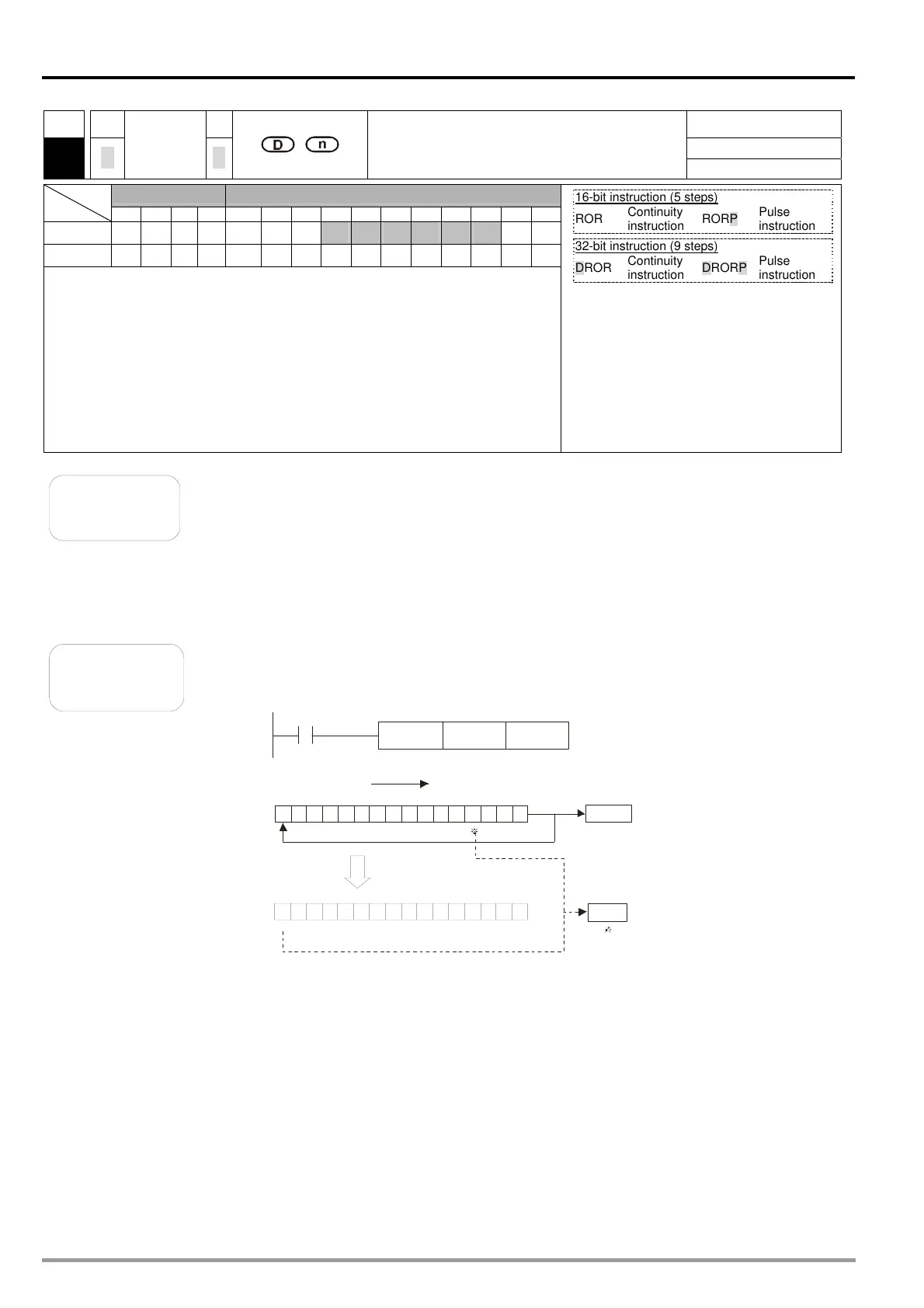
Example
When X0 is turned from OFF to ON, the bits in D10 are divided into groups
(four bits as a group), and these groups are rotated rightwards. (The bit
marked with ※ is transmitted to a carry flag.)
011 10 101 0 0111 001
010111001111001 0
0
High byte
Low byte
*
X0
RORP
D10
K4
Rotating the bits in D10 rightwards
Rotating the
16 bits in D10
Carry flag
D10
D10
Carry flag
Low byte
High byte

 Loading...


