5 Applied Instructions and Basic Usage
DVP-20PM Application Manual
5-81
API
Applicable model
20PM
78
D
D
FROM
P
P
Reading data from a control
register in a special module
Bit device Word device
X Y M S K H KnX KnY KnM KnS T C D V Z
m
1
* *
* * * * *
m
2
* *
* * * * *
D
* * * * *
n
* *
* * * * *
Note: m
1
is in the range of 0 to 255 (16-bit instruction/32-bit instruction).
m
2
is in the range of 0 to 499 (16-bit instruction/32-bit instruction).
n is in the range of 1 to (500-m
2
) (16-bit instruction).
n is in the range of 1~(500-m
2
)/2 (32-bit instruction).
The instruction supports V devices and Z devices. (If the 16-bit
instruction is used, Z devices can not be used. If the 32-bit
instruction is used, V devices can not be used.)
16-bit instruction (9 steps)
FROM
Continuity
instruction
FROMP
Pulse
instruction
32-bit instruction (17 steps)
DFROM
Continuity
instruction
DFROMP
Pulse
instruction
Please refer to the additional remark below.
Explanation
m
1
: Special module number (m
1
is in the range of 0 to 255.); m
2
: Control
register number (m
2
is in the range of 0 to 499.); D: Device in which the data
read will be stored; n: Quantity of data which will be read (16-bit instruction:
1~(500-m
2
); 32-bit instruction: 1~(500-m
2
)/2
A DVP-10PM series motion controller can read the data in a control register in
a special module by means of the instruction.
Please refer to the additional remark on the instruction TO for more information
about the numbering of special modules.
Example
The value in CR#29 in special module 0 is read, and then stored in D0 in the
motion controller used. The value in CR#30 in special module 0 is read, and
then stored in D1 in the motion controller used. The two values are read at the
same time.
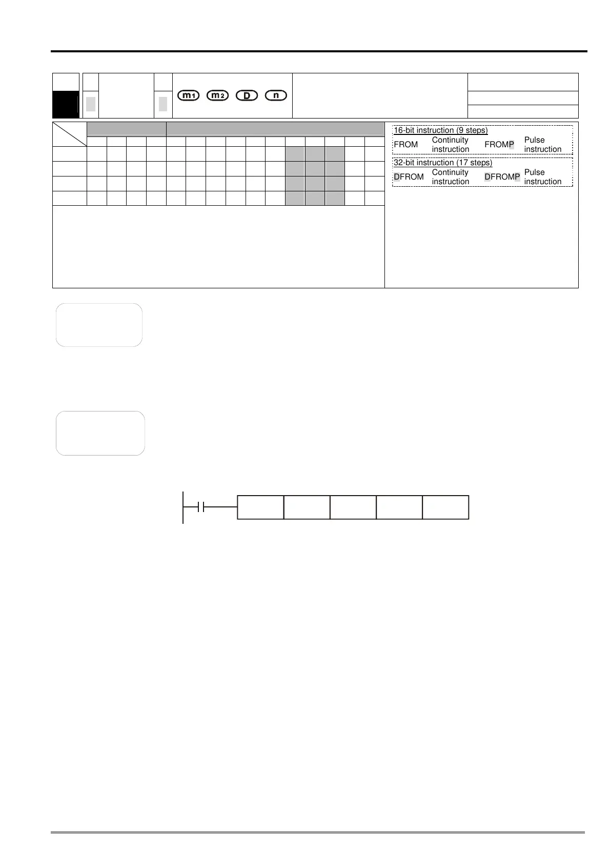
When X0 is ON, the instruciton is executed. When X0 is turned OFF, the
instruction is not executed, and the values which are read remain unchanged.
X0
FROM K0 K29 D0 K2
 Loading...


