5 Applied Instructions and Basic Usage
DVP-20PM Application Manual
5-122
API
Applicable model
20PM
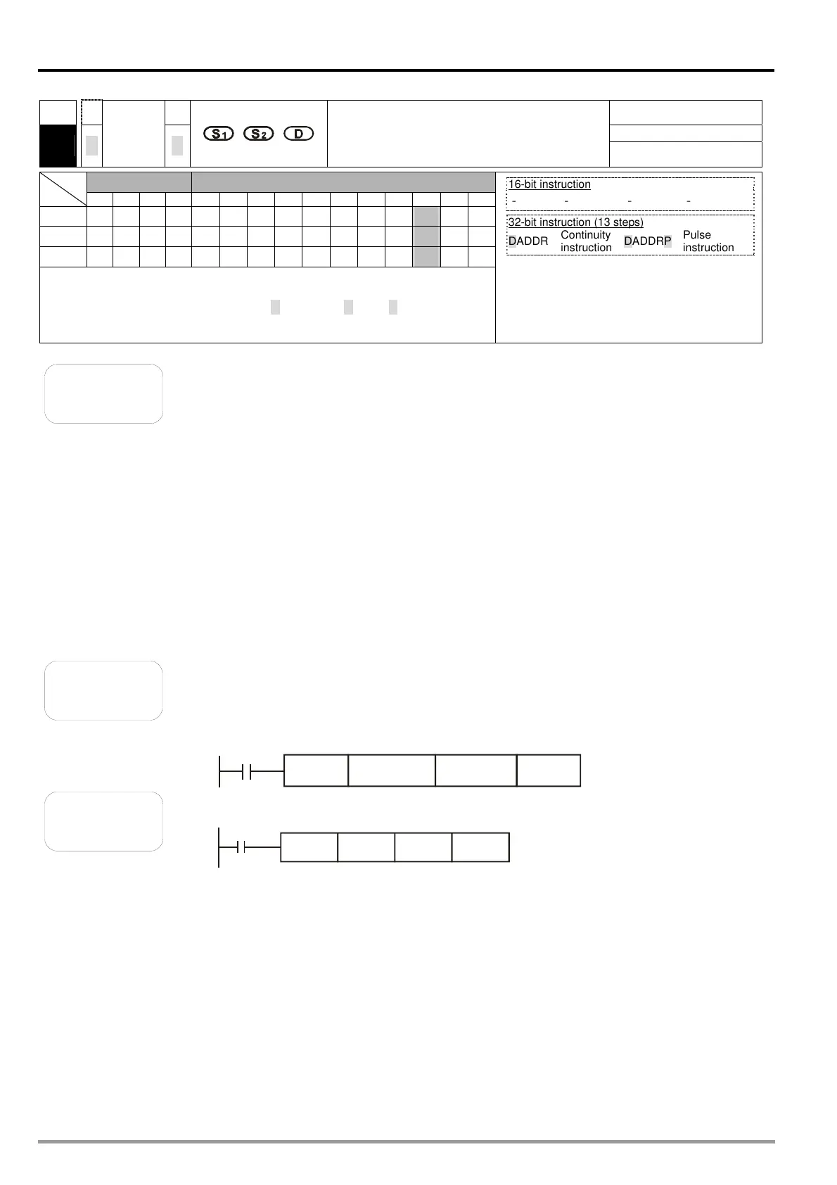
172
D
D
ADDR
P
P
Floating-point addition
Bit device Word device
X Y M S F H KnX KnY KnM KnS T C D V Z
S1
*
S2
*
D
*
Note: Please refer to specifications for more information about device
ranges.
Only the 32-bit instructions DADDR and DADDRP are valid.
16-bit instruction
- - - -
32-bit instruction (13 steps)
DADDR
Continuity
instruction
DADDRP
Pulse
instruction
Flags
Ox O100
M1808 M1968 Zero flag
M1809 M1969 Borrow flag
M1810 M1970 Carry flag
Please refer to the additional remark below.
Explanation
S
1
and S
2
can be floating-point values.
S
1
: Augend; S
2
: Addend; D: Sum
S
1
and S
2
can be floating-point values (e.g. F1.2), or data registers in which
floating-point values are stored.
If S
1
and S
2
are data registers in which floating-point values are stored, the
function of API 172 DAADR is the same as the function of API 120 DEADD.
The floating-point value in S
2
is added to the floating-point value in S
1
, and the
sum is stored in D.
S
1
and S
2
can be the same register. If the instruction DAADR is used under the
circumstances, the value in the register is added to itself whenever the
conditional contact is ON in a scan cycle. Generally, the pulse instruction
DADDRP is used.
If the absolute value of an oepration result is greater than the maximum
floating-point value available, a carry flag will be ON. If the absolute value of an
oepration reuslt is less than the minimum floating-point value available, a
borrow flag will be ON. If an operation result is 0, a zero flag will be ON.
Example 1
When X0 is ON, the floating-point value F2.200E+0 is added to the
floating-point value F1.200E+0, and the sum F3.400E+0 is stored in (D11,
D10). (The floating-point value F1.2 is represented by the scientific notation
F1.200E+0 in a ladder diagram. The number of decimal places which are
displayed can be set by means of the View menu in WPLSoft.)
X0
DADDR F1.200E+0
D10
F2.200E+0
Example 2
When X0 is ON, the floating-point value in (D3, D2) is added to the
floating-point value in (D1, D0), and the sum is stored in (D11, D10).
X0
DADDR D0 D2 D10

 Loading...


