5 Applied Instructions and Basic Usage
DVP-20PM Application Manual
5-265
State output pin
Name Function
Data
type
Time when there is
a transition in an
output pin’s signal
from low to high
Time when there is a transition in an
output pin’s signal from high to low
Error
i
An error occurs
BOOL
Input values are
incorrect.
The source
There is a transition in the Error
output pin’s signal from high to low
when there is a transition in the
n the motion
cont
rol func
tion
block.
spec
ified has
been occupied.
Enable input pin’s
signal from high
to low.
3. Troubleshooting
Error Troubleshooting
The values of input pins in the motion control Check whether the values of the input pins are in the
function block are incorrect. ranges allowed.
4. Example
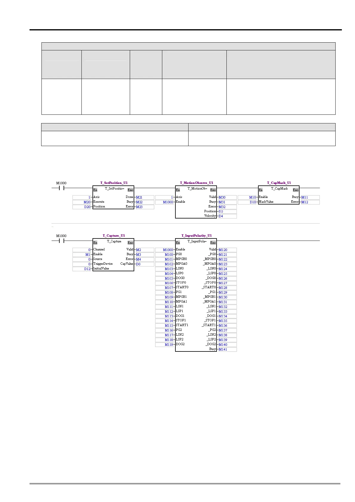
A high-speed capturer and the motion control function block T_CapMask are used. If the present
position of the first axis is in the range (the value of the CapValue output pin±the value of the
MaskValue input pin) which is masked, it will not be captured after an external device is set to ON.
After the program is executed, the present posit e present speed of the first
axis will be read.
After the value in D20 is set to 0, and M
value 00. Af 1 is e
Setting high-speed capturer 0: If PG0 is turn t position of the first axis will be
captured.
Set the value in D10 to 500. Af
started.
After M100 ere wil f
the CapVal ill s
After the va
After M100 is set to ON, there will be of
the CapValue output pin will still be 1
After the value in D20 is set to 600, a ill output 600 pulses.
Aft M100 s set to ON, there will be a transition in PG0’s sig al from low to high, and the value of
ion of the first axis and th
20 is turned ON, the
turned ON, high-spe
ed
ON, the presen
first axis will output 0 pulses
d capturer 0 will be started.
Set the in D12 to 1 ter M
ter M10 is turned
ON, the h
l be a transition in PG0’s s
00.
nd M20 is turned ON.
a transition in PG0’s s
00.
nd M20 is turned ON.
igh-speed masking specified will be
ignal from low to high, and the value o is set to ON, th
ue output pin w
lue in D20 is set to 500, a
till be 1
The first axis will output 500 pulses.
ignal from low to high, and the value
The first axis w
er i n