11 CANopen Communication Card
CR#020: CANopen bus communication status
[Description]
Two consecutive bits in the control register are used to display a node communication status.
00: Disconnected
01: Connected
11: Ready
Please refer to the table below for more information.
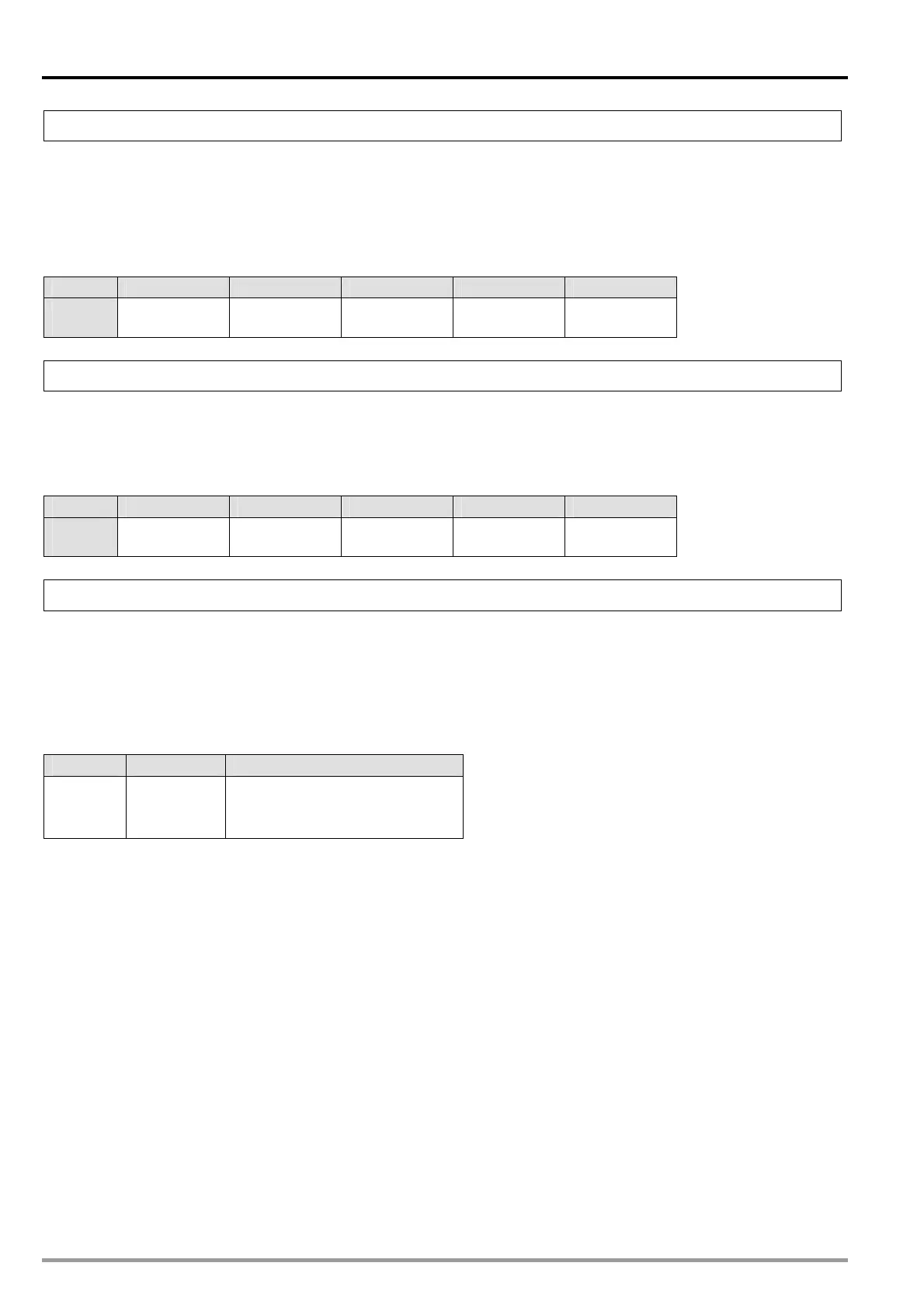
Bit Bit [15:8] Bit [7:6] Bit [5:4] Bit [3:2] Bit [1:0]
Node
number
Reserved Node 4 Node 3 Node 2 Node 1
CR#040: Error status of a server
[Description]
The control register is used to display the error status of a servo drive. Bit 0~bit 3 in CR#010
correspond to node 1~node 4. If an error occurs, its corresponding bit will be 1. If an error reset
command is executed, the contents of the register will be cleared automatically. Please refer to the
table below for more information.
Bit Bit [15:4] Bit [3] Bit [2] Bit [1] Bit [0]
Node
number
Reserved Node 4 Node 3 Node 2 Node 1
CR#050: CANopen bus control command
[Description]
The control register is used to send bus control commands to the nodes connected successfully in a
CANopen network. If the value in the control register is 1, the servos which have been connected are
ON. If the value in the control registers is 128, the servos which have been connected are OFF. If the
value in the control register is 129, the errors which appear are cleared. After the setting of the control
register is completed, the contents of the register will be cleared automatically. Please refer to the table
below for more information.
Bit Bit [15:8] Bit [7:0]
Value Reserved
1: All servos are ON.
128: All servos are OFF.
129: All errors are cleared.
DVP-20PM Application Manual
11-8

 Loading...


