EPSON Stylus Pro 9000
Appendix 167
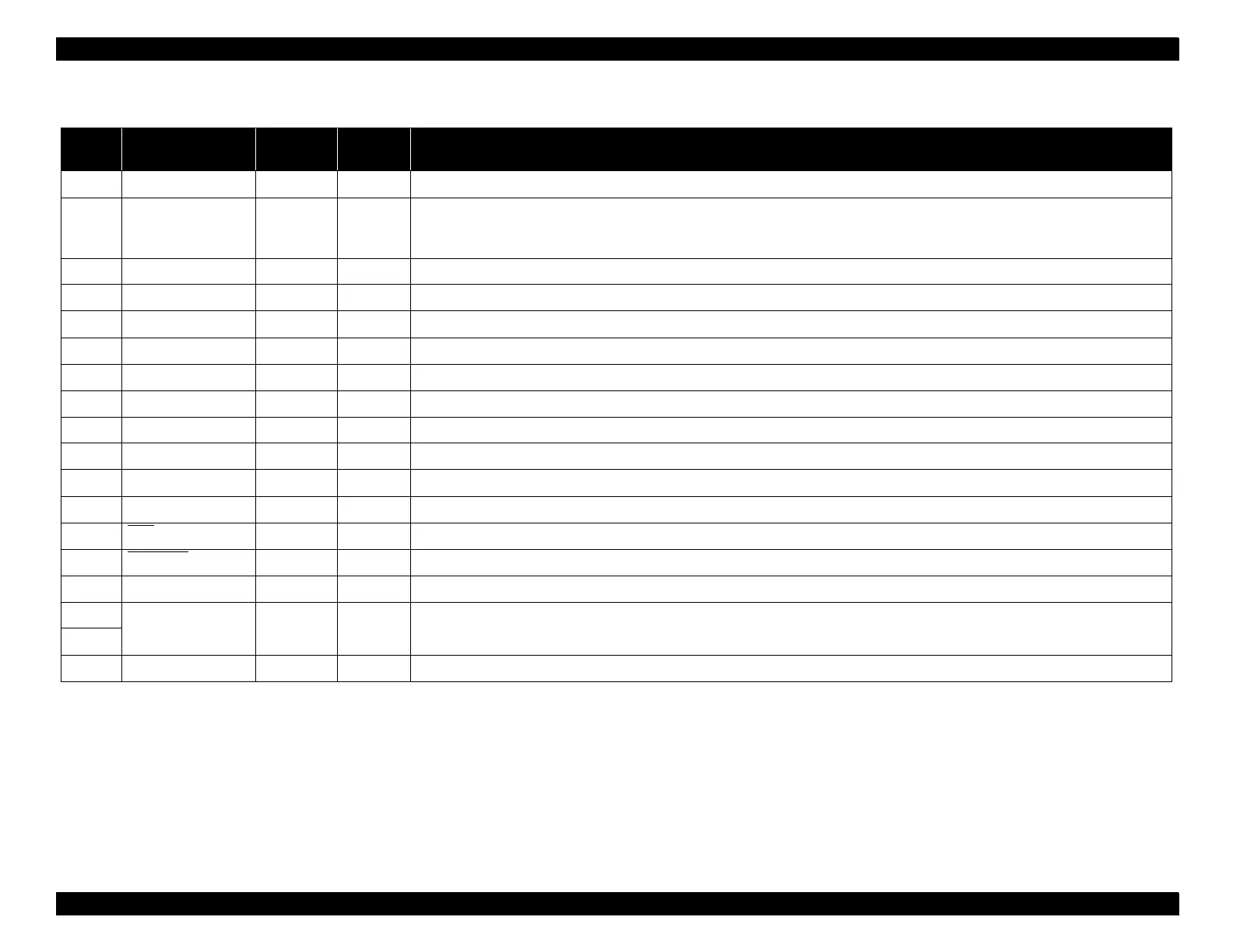
Table 7-9. Pin Assignment for Reverse Channel
Pin No. Signal Name Return
GND Pin
Direction Functional Description
1 HostClk 19 In Host clock signal.
2-9 Data0-7 20-27 In
The DATA0 through DATA7 signals represent data bits 0 to7, respectively. Each signal is at high level when data is logical
1 and low level when data is logical 0. These signals are used to transfer the 1284 extensibility request values to the
printer.
10 PeriphClk 28 Out Printer clock signal.
11 PeriphAck/PtrBusy 29 Out Printer busy signal and reverse channel transfer data bit 3 or 7.
12 AckData Req 28 Out Acknowledge data request signal and reverse channel transfer data bit 2 or 6.
13 Xflag 28 Out X-flag signal and reverse channel transfer data bit 1 or 5.
14 HostBusy 30 In Host busy signal.
15 NC Not connected.
16 GND Signal ground.
17 Chassis GND Chassis ground.
18 Logic-H Out Pulled up to +5V via 3.9K ohm resister.
19-30 GND Ground for twisted pair return.
31 INIT
30 In Not used.
32 DataAvail
29 Out Data available signal and reverse channel transfer data bit 0 or 4.
33 GND Ground for twisted pair return.
34 NC Not connected.
35 +5V — Out Pulled up to +5V via 3.3K ohm resister.
36 1284-Active 30 In 1284 Active Signal.

 Loading...


