EPSON Stylus Pro 9000
Disassembly & Assembly 78
REMOVING THE PLATEN GAP ADJUSTMENT MOTOR
Preparation:
Remove the Maintenance Cover as described in Maintenance Cover
Removal on page 58.
Remove the Top Cover as described in Top Cover Removal on page 59.
Remove the Right Side Cover as described in Left and Right Side Cover
Removal on page 60.
1. Disconnect the cables from CN17 and CN18 on the relay board.
2. Remove the two screws (CP(W2) M3x8) securing the PG Motor to the side
frame, and then remove the motor.
Figure 4-35. PG Motor Removal
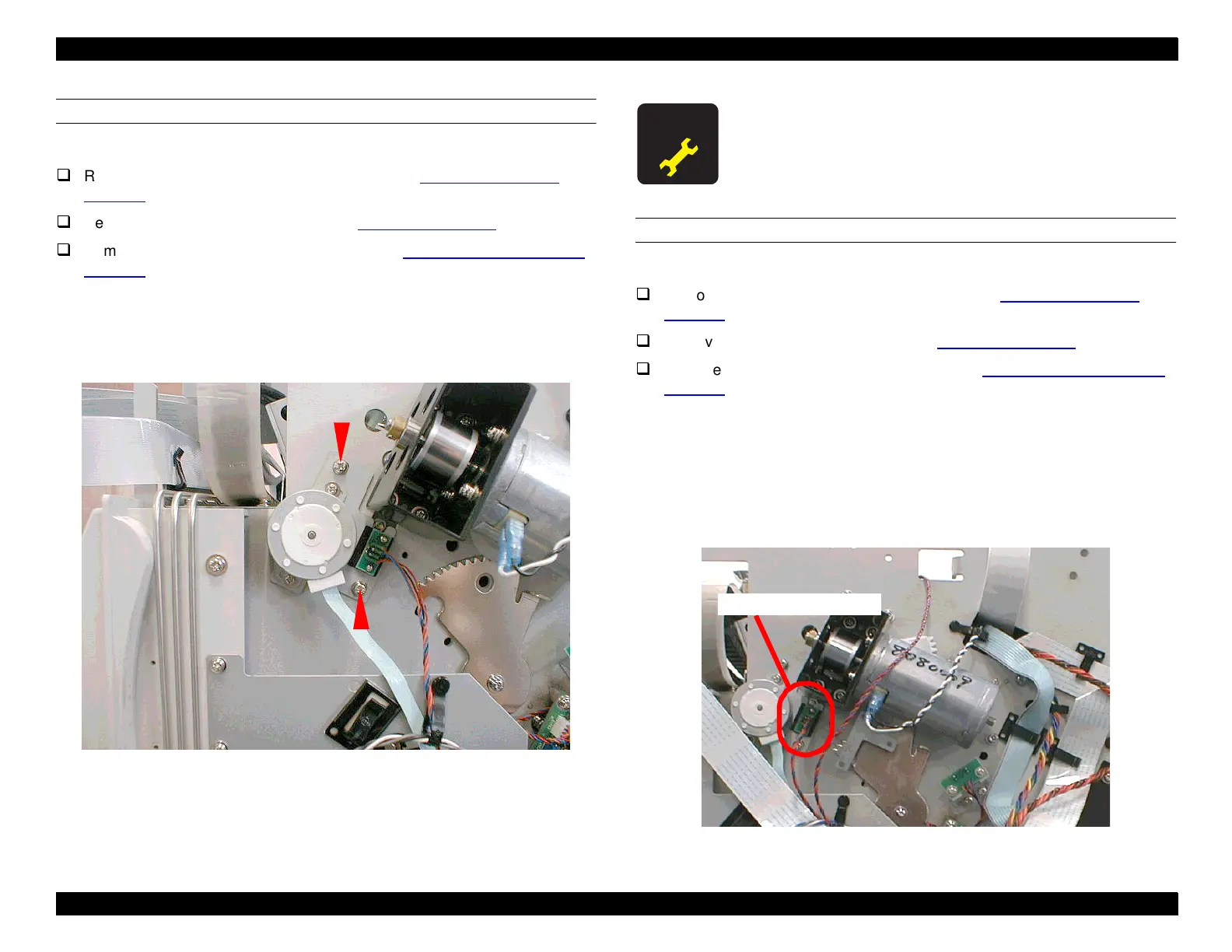
REMOVING THE PLATEN GAP HOME POSITION SENSOR
Preparation:
Remove the Maintenance Cover as described in Maintenance Cover
Removal on page 58.
Remove the Top Cover as described in Top Cover Removal on page 59.
Remove the Right Side Cover as described in Left and Right Side Cover
Removal on page 60.
1. Disconnect the cable from CN17 on the relay board on the right side of the
printer.
2. Remove the two screws securing the Platen Gap HP Sensor to the PG
Adjustment Motor mounting plate, and then remove the sensor.
NOTE:
A No. 1 (small) Phillips screwdriver is needed to remove these
screws.
Figure 4-36. Removing the Platen Gap HP Sensor
After reinstalling the PG Motor, perform the gear backlash
adjustment.
Platen Gap HP Sensor

 Loading...


