EPSON Stylus Pro 9000
Technical Overview 37
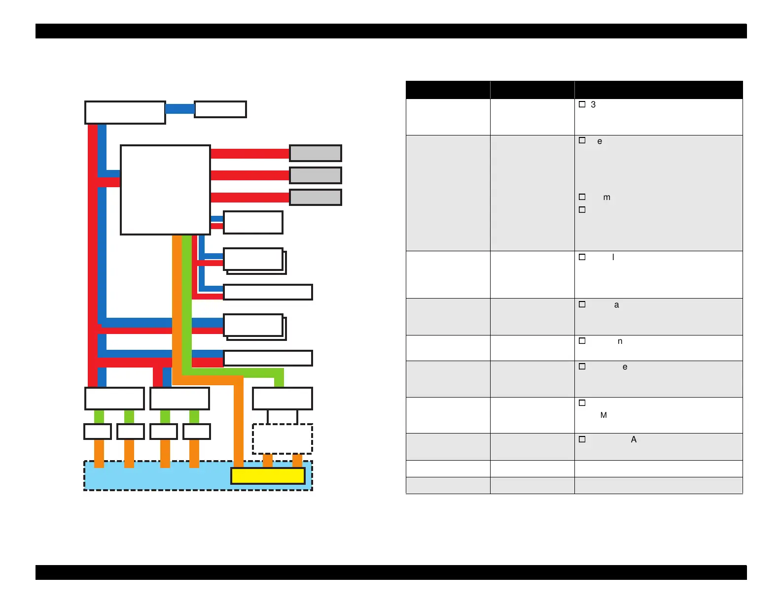
2.2.6 Control Circuit
This section summarizes the functions of the (C277MAIN) Main Board.
Figure 2-16. C277MAIN Board-Circuit Block Diagram
IC8
CPU/C90A08CA
(SH7043)
CN7
Control Panel
IC13
ASIC/E05B61AA
CN2
Type-B Slot
CN3
Mac Serial I/F
CN1
Parallel I/F
IC39
SRAM/8KB
IC18/19
DRAM/2MB
CN19
RAM-SIMM/16MB
IC1/2
Flash mem./1MB
Fixed
-Firmware
-Setting parameters
CN20
PC Card connector
IC32
ASIC/uPD65802
IC20
ASIC/TE7751
IC37
DAC/M65530FP
IC33
Head-drive voltage
common driver
Printheads (B/C)
CR
Motor
PF
Motor
PG
Motor
Pump
Motor
Printer
mechanism
Motor
drivers
B head C head
Head-drive wave
generation
Head data & control signals
IC35
IC30
IC31
Table 2-7. C277MAIN Board Main Components
Name/Code Location Function
CPU (C90A08CA)
SH7043
IC8
32 bit RISC-CPU
Clock speed = 33MHz
128KB PROM internal
ASIC (E05B61AA) IC13
Regulates print data
Command handling
Rasterizer (image data handling)
Head drive regulation (DAC)
Print timing regulation
Memory (DRAM/SRAM)
I/F Circuit Control
Parallel interface (IEEE1284)
Macintosh Serial interface
Type-B
ASIC (TE7751) IC20
Regulates Motor
Pump Motor
PG Motor (PG setting)
Fan (PS, Paper Suction)
ASIC (uPD65802) IC32
Regulates motor (PWM regulation)
CR Motor
PF Motor
DAC (M65530FP) IC37
3 channel 10 bit DA converter
head-drive voltage control
Flash Memory
(MBM29F400TC)
IC1/2
Flash Memory (1Mbyte)
Save firmware
Register setting parameters
DRAM (EDO) IC18/19
EDO RAM
2Mbyte
16Mbtye (CN19 mounted SIMM)
SRAM (LC3564SM-
10)
IC39
64Kbit SRAM
External data ring buffer type
Driver IC (L6203) IC33/35 CR/PF Motor Driver
Driver IC (LB1845) IC30/31 PG/Pump Motor Driver