EPSON Stylus Pro 9000
Disassembly & Assembly 69
MAINTENANCE ASSEMBLY REMOVAL & DISASSEMBLY
When replacing the Waste Ink Pads, you also have to replace other parts (see
Maintenance Procedures
on page 67). Refer to the steps below to replace the
following:
Right Flushing Box
Pump Mechanism
Capping Mechanism
Head Cleaning Blade
Preparation:
Remove the Maintenance Cover as described in Maintenance Cover
Removal on page 58.
Remove the Top Cover as described in Top Cover Removal on page 59.
Remove the Right Side Cover as described in Left and Right Side Cover
Removal on page 60.
Remove the Lower Paper Guide as described in Lower Paper Guide
Removal on page 63.
Remove the right-side Waste Ink Box as described in Replacing the Waste
Ink Pads on page 67.
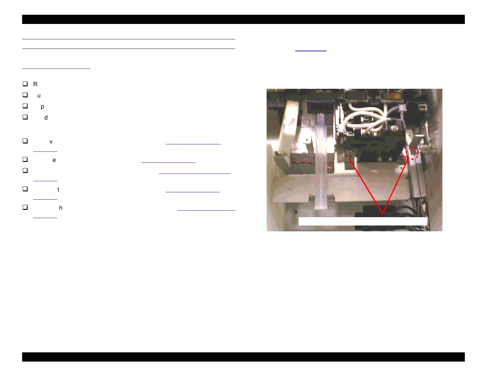
1. Disconnect CN9 and CN19 from the relay board on the right side of the
printer. See Figure 4-21
.
2. Remove two screws (CP(W2) M4x6) securing the Maintenance Assembly
to the printer as shown below. Access the screws from underneath the
Maintenance Assembly. (The screw on the right is hidden, so you may
have to get down very low to see it.)
Figure 4-20. Maintenance Assembly Removal - 1
Two screws (the one on the right is hidden)

 Loading...


