EPSON Stylus Pro 9000
Disassembly & Assembly 70
3. From the right side of the printer, remove the one remaining screw
(CP(W2) M3x6) securing the Maintenance Assembly to the printer, and
then remove the Maintenance Assembly.
Figure 4-21. Maintenance Assembly Removal - 2
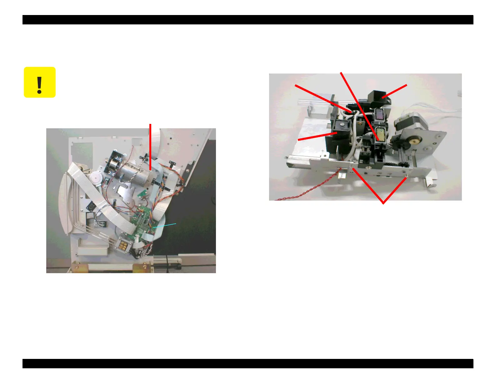
4. Remove the two screws (CP(W2) M3x6) securing the Carriage Lock to the
Maintenance Assembly, and then remove the Carriage Lock.
Figure 4-22. Disassembling the Maintenance Assembly - 1
5. Remove the two screws (CP(W2) M3x6) securing the Capping Mechanism
to the frame of the Maintenance Assembly. Lift the Capping Mechanism off
the frame (it’s still attached to the Pump Mechanism by the ink tubing).
6. Remove the Pump Drive Shaft.
7. Remove the screw (CP(W2) M3x6) securing the Pump Mechanism to the
frame of the Maintenance Assembly, and then remove the Pump
Mechanism along with the Capping Mechanism.
8. Remove the screw securing the Flushing Box to the frame of the
Maintenance Assembly, and then remove the Flushing Box.
CAUTION
When removing the Maintenance Assembly, the tubes that
drain ink into the Waste Ink Pads may leak or drip ink. It’s a
good idea to wipe off the ends of these tubes before
removing the Maintenance Assembly.
One screw
Relay Board
Screws securing
capping mechanism
to frame
Capping Mechanism
Carriage
Lock
Right
Flushing Box
Pump
Mechanism

 Loading...


