EPSON Stylus Pro 9000
Disassembly & Assembly 79
REMOVING THE COVER OPEN SENSORS
The Cover Open Sensors (interlock switches) are a safety feature to detect the
position of the Front Cover (open or closed). There are two switches (right and
left). Printing stops when the cover is open.
Preparation (to remove the right interlock switch):
Remove the Maintenance Cover as described in Maintenance Cover
Removal on page 58.
Remove the Top Cover as described in Top Cover Removal on page 59.
Remove the Right Side Cover as described in Left and Right Side Cover
Removal on page 60.
To remove the left interlock switch, also do the following:
Remove the Left Side Cover as described in Left and Right Side Cover
Removal on page 60.
Remove the Upper Paper Guide as described in Upper Paper Guide
Removal on page 64.
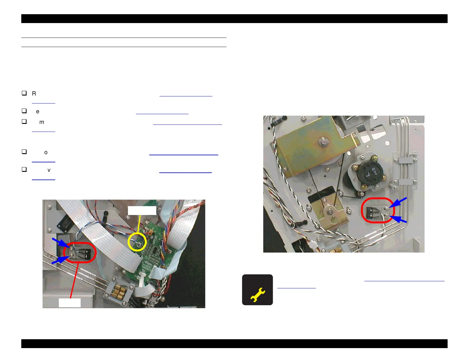
1. To remove the Right Interlock Switch, disconnect the cable from CN13 on
the relay board as shown below.
Figure 4-37. Interlock Switch (R) Removal
2. Remove the two screws (CP(W2) M3x6) securing the Interlock Switch
mounting plate to the side frame, and remove the Interlock Switch together
with the plate.
3. To remove the Left Interlock Switch, disconnect the cable from CN27 on
the C277MAIN board.
4. Remove the two screws (CP(W2) M3x6) securing the Interlock Switch
mounting plate to the side frame, and remove the Interlock Switch together
with the plate.
Figure 4-38. Interlock Switch (L) Removal
CN13
Switch
Perform the adjustment for the
Cover Open Sensor Assembly
(Right and left)
on page 135.
 Loading...


