EPSON Stylus Pro 9000
Disassembly & Assembly 93
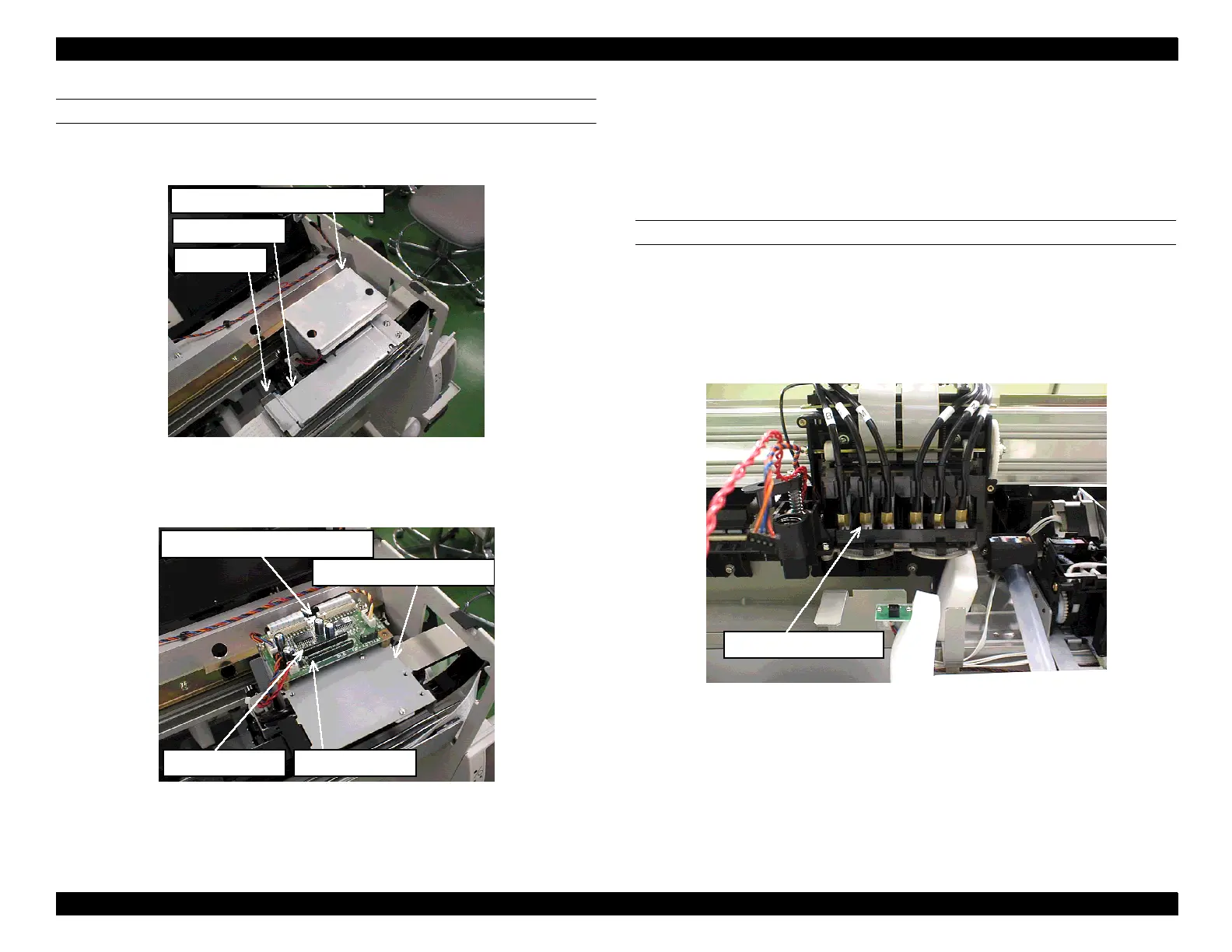
REMOVING THE CR CIRCUIT BOARD
1. Remove the CR circuit board guide plate, cut the insulation (plastic) lock tie
next to the Ferrite core, and remove the cable support.
NOTE:
You may dispose of the CR circuit board guide and cable support.
2. Remove two printhead FFCs and four connectors. (CN9 is not in use.)
3. Remove 4 flat core pieces from the tape wires (two from the FFCs to the
printheads and two from the FFCs to the junction board). Remove the
metal snaps securing the ferrite core and then remove the ferrite core
pieces.
4. Remove the CR circuit board.
DISCONNECTING THE INK DAMPERS
1. While holding down the cutter, remove the carriage cover.
2. Remove the cutter and cutter solenoid.
3. Cut the insulation (plastic) lock ties that hold the ink tubes in place.
4. Loosen the damper joint screws and remove the ink tubes from the
dampers.
5. Remove the H cable pressing plate (black) that secures the printhead
FFCs to the inside of the cable connection plate.
CR circuit board guide plate
Cable support
Ferrite core
CR circuit board assembly
Cable connection plate
CR tape wire 1 CR tape wire 2
Damper joint screw