Fire Alarm Computer 8000C / M
Page 103
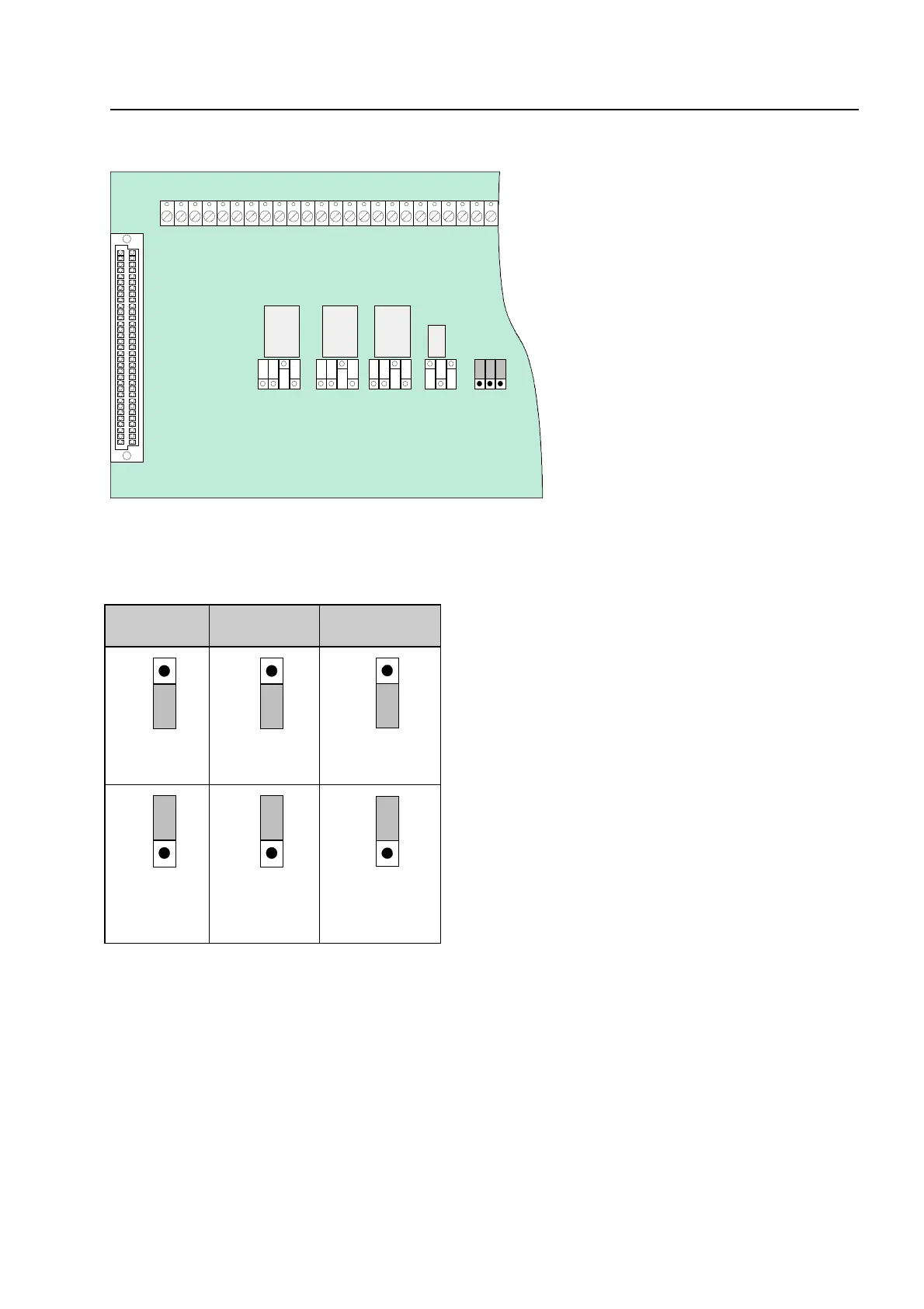
CPU failure mode function of relays K2, K3 and K4
BR 5
BR 4
BR 3
Fig. 47: Location of the emergency mode jumpers BR3-5 on the field device module
K4 K2 K3
R 5
R 4
R 3
Jumper X in position 1/2
No activation of the relay while the fire alarm
control panel is in CPU failure mode. (state on
leaving factory)
R 5
R 4
R 3
Jumper X in position 2/3
Relay also activated while the fire alarm control
panel is in CPU failure mode.
Used if a common function is programmed for the
relays, such as
common fire, common alarm
and
common disconnection
.
Field device modu