Page 114
Fire Alarm Computer 8000C / M
12.1 Analog loop module esserbus
®
Part no. 784382)
The analog loop module enables you to connect the analog loop - the
esserbus
®
. The analog loop
is configured with Customer Data Editor
8000C / M
.
Module Index from B2, C1 or higher required.
Caution: Do not connect analog loop module with Index C !
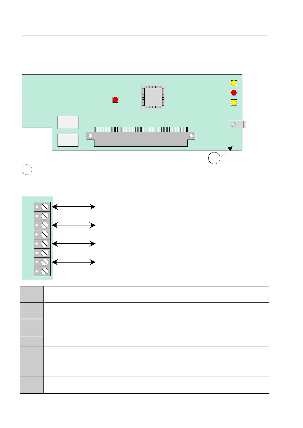
Terminal card assignment
1
2
3
4
5
6
7
8
X 1
64-way plug connector to micro module slot of the basic module, field device module or
extension module of the FACP 8000C / M
K1,K 2
Bi-directional loop interrogation by loop isolators
(K1 = A+, A- / K2 = B+, B-)
LED 1
(SMD) red flashing
⇒
in normal mode in time with communication on the loo
(SMD) red lit steadily
⇒
Short circuit on analog loop
LED 2
(SMD) yellow lit steadliy
⇒
Module faulty
LED3
(SMD) red flashing
⇒
+24V supply voltage failure or communication to
control panel processor interrupted
(SMD) red lit steadily
⇒
Module in CPU failure mode
(control panel CPU failure)
LED4
(SMD) yellow flashing
⇒
Processor program running - normal mode
(SMD) yellow flashing rapidly
⇒
Module in test mode
nalog loop module
 Loading...