Page 98
Fire Alarm Computer 8000C / M
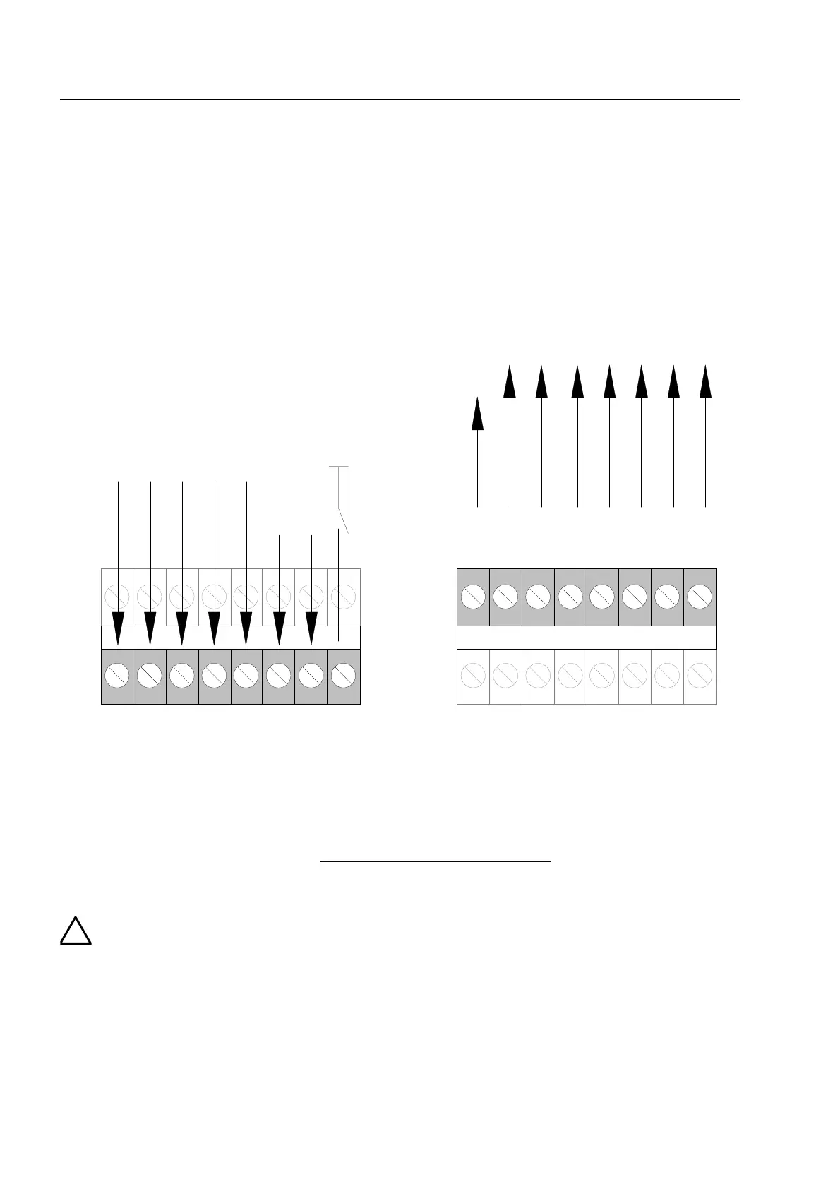
11.3 Connecting a fire department operating panel
A fire department operating panel may be connected to terminals X4-X7. Wiring differs from area
to area and is governed by the requirements of the regional fire department.
do not use
FD call LED on (IN1 on GND)
(closer)
MB disconnected
acoustic signals off
CHECK MB
reset FACP
fire control off
(revision)
N1
N8
N2
N3
N4
N5
N6
N7
MB activated
extingguishing
system activated
common fire
MB disconnected
OUT1
OUT8
OUT2
OUT3
OUT4
OUT5
OUT6
OUT7
MB activation
prevent
do not use
do not use
acoustic signals o
fire control off
(revision)
bottom
terminals
erminals
bottom
terminals
top
terminals
Fig. 40: Connection terminal for the fire department operating panel
Outputs (OUT1 to OUT 8) at the fire department operating panel interface may have a
maximum load current intensity of no more than 25 mA per output
.
If the inspection input (terminal IN8) is not used, jumper BR21 must always be fitted a
position 1-2 !
ield device module