Page 82
Fire Alarm Computer 8000C / M
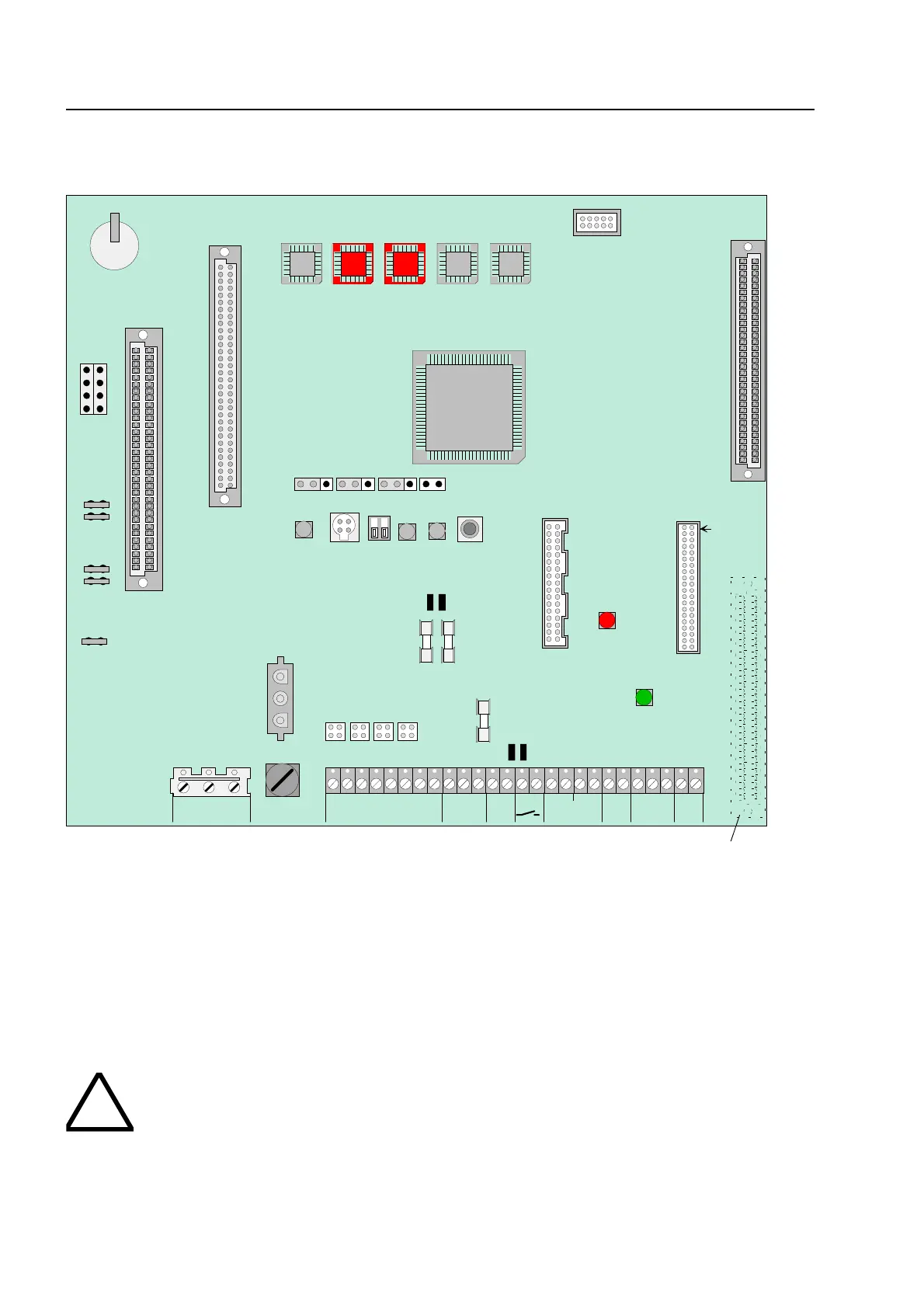
10 Basic module of the FACP 8000C / M
X21
X20
transformator
terminals
I
I
Slot for micro module
Slot for power supply module
X17
X16
Operating modulel
Printer connection
Plug 1
X22
X23
1 2 3 4
Fig. 26: Basic module
* Terminal 2 (Plug 2) is equipped only by FACP 8000M (next Page see Table).
Replacing the operating system software
When replacing the operating system software (EPROM D6 + D7), the customer data is
automatically deleted. Before changing the EPROM, save your data on the hard disk of the service
PC. After installing the new operating system software, the customer data can be transferred back
from the service PC to the FACP 8000C / M.
To prevent short circuits
All connected power and signal lines must be secured using appropriate fasteners, e.g
plastic cable binders. Make sure the mains cable will not move and touch the signa
lines. Remove all power (mains and battery) from the fire alarm system before any wor
is carried out.
asic module