EasyManua.ls Logo

Esser 8000C - 1 Connecting the Relays K2, K3, K4

Esser 8000C
190 pages
Print Icon
To Next Page IconTo Next Page
To Previous Page IconTo Previous Page
Loading...
Page 102
Fire Alarm Computer 8000C / M
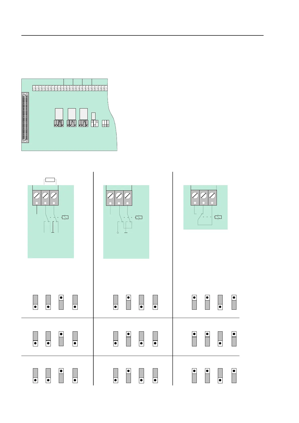
11.4.1 Connecting the Relays K2, K3, K4
Jumpers are used for adjusting the three relays K2, K3 and K4 to a variety of requirements. The
three relays may be coded independently of each other as
positive-switching and monitored
,
positive-
switching
or as
potential-free change-over contact
.
BR19
BR18
BR17
BR15
BR14
BR13
BR11
BR10
BR 9
G
Ö
S
K4
K1
G
Ö
S
K3
G
Ö
S
K2
BR12
BR16
BR20
K3
K4
K2
1
2
3
1
2
3
1
2
3
Fig. 46: Location of the relay K2,K3,K4 and the jumpers BR9-20 on the field device module
G
Ö
S
K
BR 9
BR 10
BR 11
1
2
3
BR 12
1
2
3
positive-switching/monitored
change over
K2
BR 13
BR 14
BR 15
BR 16
K3
BR 17
BR 18
BR 19
BR 20
K4
BR 9
BR 10
BR 11
BR 12
K2
BR 13
BR 14
BR 15
BR 16
K3
BR 17
BR 18
BR 19
BR 20
K4
BR 9
BR 10
BR 11
BR 12
K2
BR 13
BR 14
BR 15
BR 16
K3
BR 17
BR 18
BR 19
BR 20
K4
1
2
3
1
2
3
1
2
3
1
2
3
1
2
3
1
2
3
1
2
3
1
2
3
1
2
3
1
2
3
1
2
3
1
2
3
1
2
3
1
2
3
1
2
3
1
2
3
1
2
3
1
2
3
1
2
3
1
2
3
1
2
3
1
2
3
1
2
3
1
2
3
1
2
3
1
2
3
1
2
3
1
2
3
1
2
3
1
2
3
1
2
3
1
2
3
1
2
3
1
2
3
positive-switching
G
Ö
S
+monitoring
K
G
Ö
S
+12V DC Ub int.
10 K
R *
K
+
-
n. c.
+12V DC Ub int.
UMess
signal in operation
+
-
n. c.
F
ield device module

Table of Contents

Related product manuals