Fire Alarm Computer 8000C / M
Page 63
8 Assembly
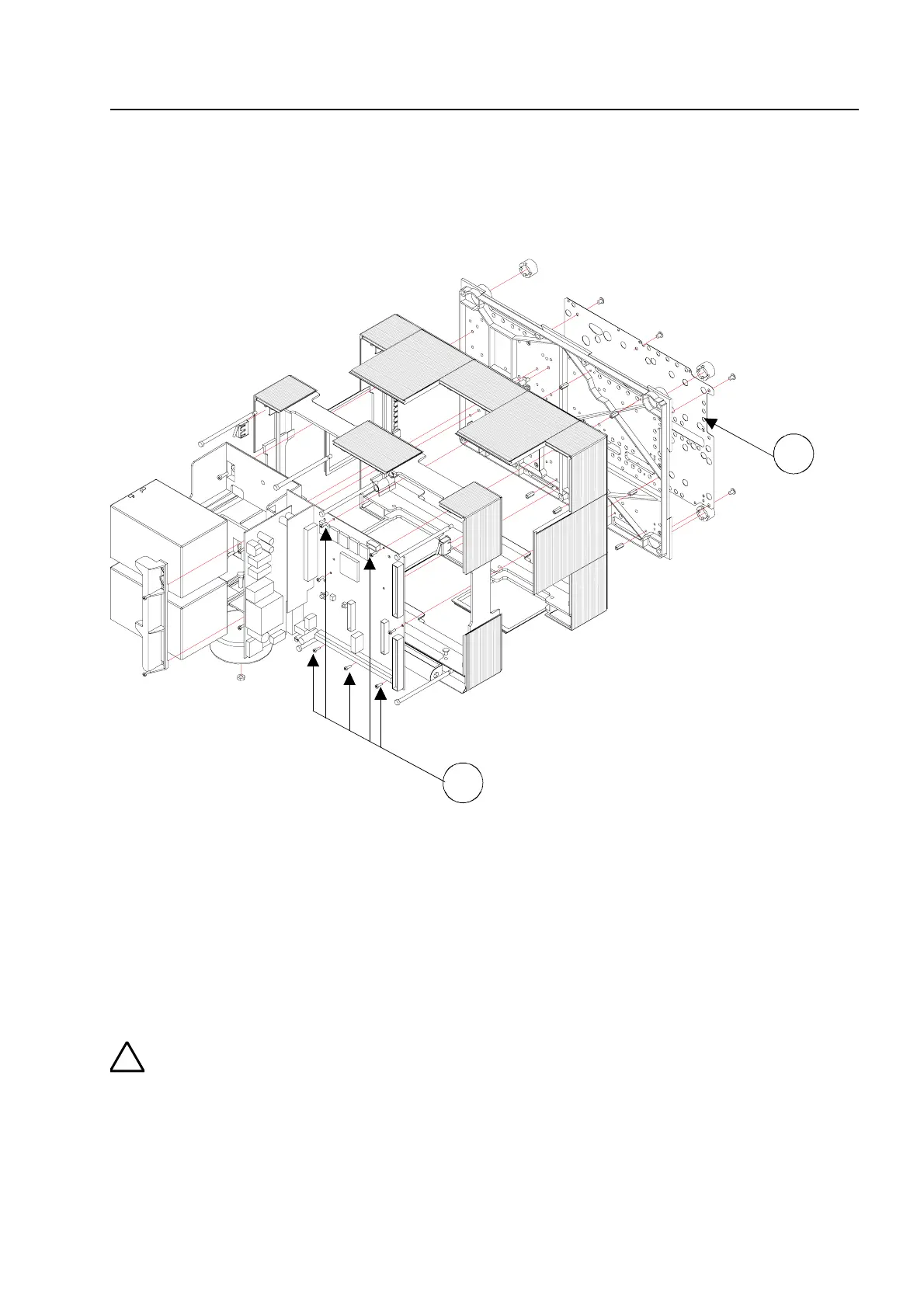
The exploded view shows a FACP 8000C with two 12 V / 12 Ah rechargeable batteries in the
battery compartment on the left and the basic module installed on the right.
Fig. 7: FACP 8000C with Standard rear panel
c
Metal sheet of the base plate for shielding and the PE connection
d
Fastening screws for the basic module.
The five fastening screws are screwed into the metal spacers. This connection establishe
an electrically conductive link with the metal plate of the main board. The basic and Fiel
device modules are connected via the metal plate to the PE mantle terminal for connectin
the PE supply lead.
The basic and Field device module is connected to the central housing’s rear metal pane
via the metal spacers and the metal screws. Without this electrically conductive connectio
between the basic module and the rear metal panel, sufficient EMC protection for th
FACP 8000C/M is not guaranteed.
Assemb