Fire Alarm Computer 8000C / M
Page 99
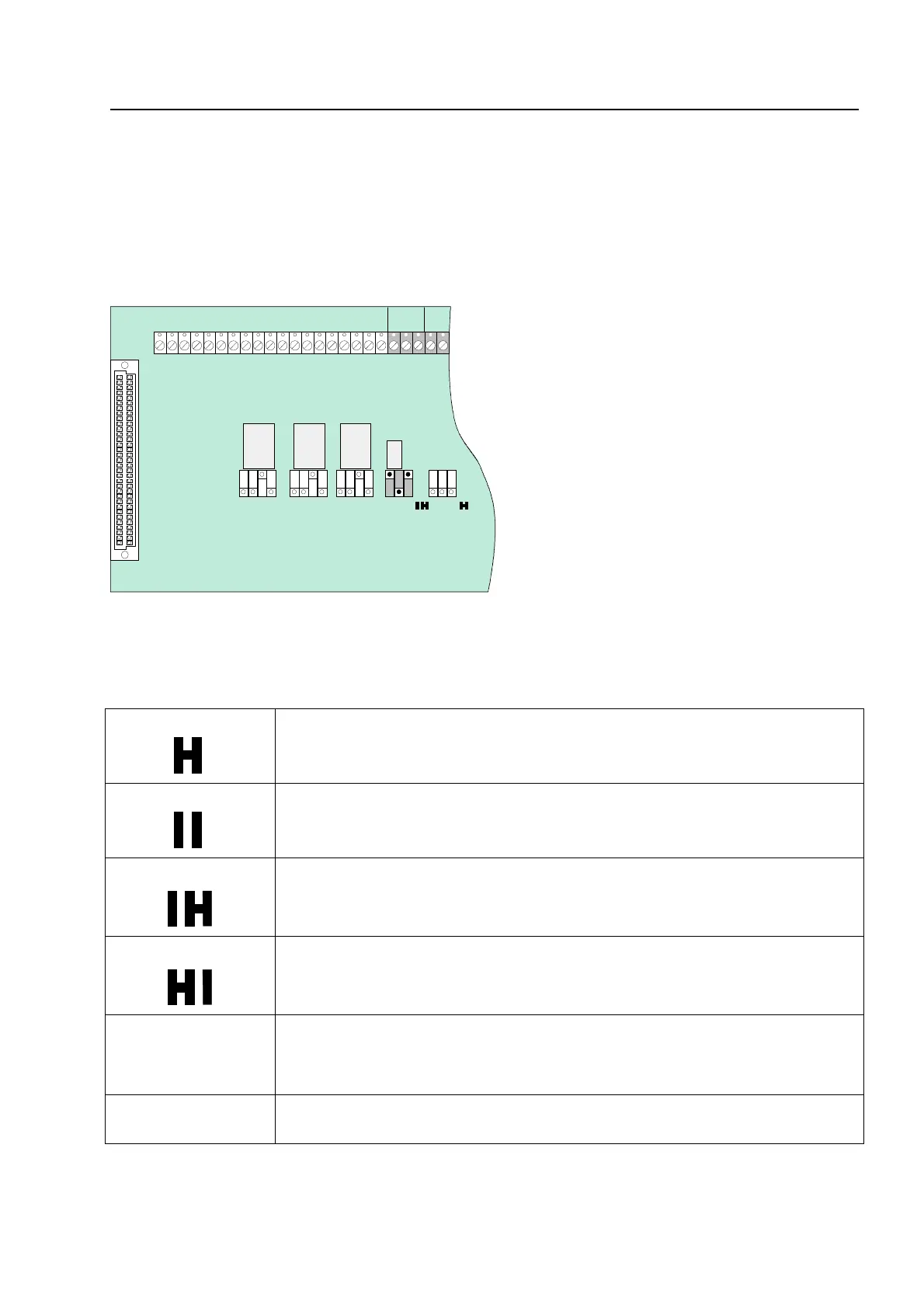
11.4 Connecting the master box (Relay K1)
Relay K1 for the connection of a master box is part of the peripheral module.
The control configuration of relay K1 can be set to
monitored and switching the positive potential,
switching the positive potential
or as a
non-monitored change-over contact
by means of jumpers
(BR6 – BR8). The setting depends on the actual requirements.
BR 8
BR 7
BR 6
RÜCK.
GND
Fig. 41: Location of the master box relay K1 and the jumpers BR 6-8 on the field device module
Setting the operating mode for relay K1
Activation of master box relay (K1) also in the event of a fire alarm with th
control panel in the CPU failure mode (state on leaving factory)
No activation of the master box in the event of CPU failure-fire
No activation of the master box in the event of a fire alarm when the cove
contact on the control panel housing is open. (State on leaving factory)
Activation of master box even with cover contact open (outer housing)
R*
Monitored end-of-line resistor R = 680
Ω
(state on leaving factory
Monitoring capability of internal resistor in master box 50-1000 ohms (refe
to customer data programming)
S*
Potential-free confirmation contact in master box
Field device modu