Fire Alarm Computer 8000C / M
Page 135
The following modes are possible:
1. Fire detector zone for connecting special fire detectors and manual call points with or without
switch-on control (ESK)
2. EDD diagnostic detector zone for connecting addressable fire detectors with individual detector
addressing and disconnection facility
3. Non-addressable TAL zones for connecting technical alarm modules
4. Addressable TAL zones configured in diagnostic detection technology for connecting technical
alarm modules
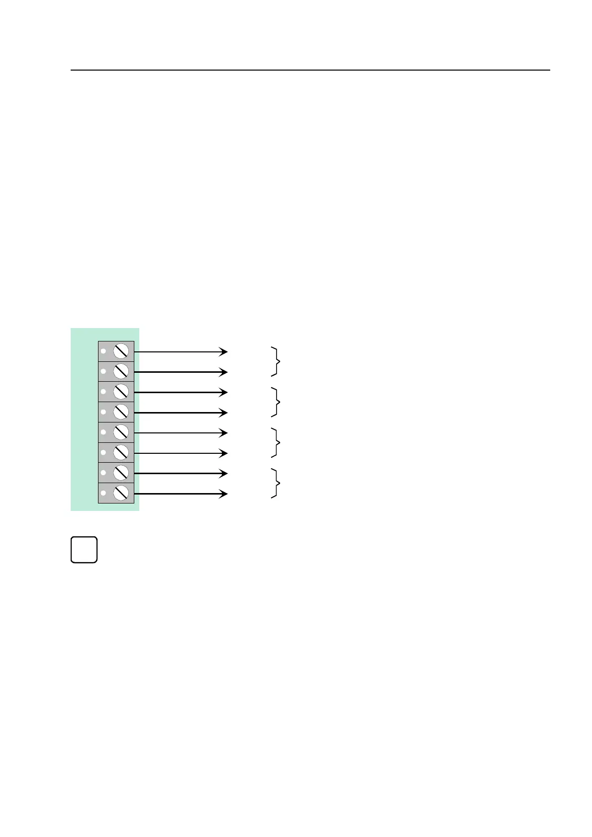
Terminal card assignment
The detector zone number (1 to 4) corresponds to the numbering on the 4-zone module. The
consecutive detector zone numbering of the fire alarm control panel is defined in the customer
data programmed with the service PC.
One zone may include a maximum of 32 automatic or 10 non-automatic fire detectors. A
detectors of one zone must be used in the same mode. Automatic and non-automatic fir
detectors should be connected to different zones. VdS guidelines do not allow mixe
mode operation!
Factory settings
On initial works delivery of the fire alarm control panel, the installed 4-zone BM modules are not
programmed in the customer data and are therefore not fitted with terminating resistors.
☞
Zone assignment and operating mode are programmed using the service PC and Customer
Data Editor 8000C / M software. For each detector zone, you may enter a specific
additional text comprising 25 characters per line for output on the alphanumeric display and
protocol printer.
4-zone modu
1
2
3
4
5
6
7
8
 Loading...