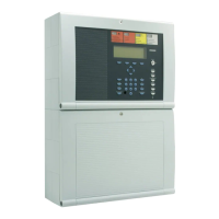
Fire Alarm Computer 8000C / M
Page 73
The extension housing is assembled similar to the central housing. The individual assembly steps
are described in the section "Assembling the central housing".
The following must also be observed when assembling the extension housing:
♦
The connection pieces between the central and extension housings can be pushed into the
housing only from the rear side due to the door hinge. If an extension housing is fitted at the
bottom to an already securely installed central housing, the central housing must be removed
from the assembly surface.
♦
A separate drilling template is available for each of the two housing variants with the standard
or battery rear panel. The drilling template is enclosed in the central unit’s additional pack.
♦
The fastening holes in the mounting surface must be drilled precisely and without offset to the
side. Otherwise, use of the connecting pieces between the two housings is no longer possible
in the event of major deviations.
☞
If the extension housing with the battery rear panel is used, please note that depending on
the rechargeable batteries used, a significant weight must be supported by the fastening
screws of the extension housing. Longer 8 mm flat-head screws should always be used
here.
☞
Each housing must be separately secured with suitable fastening materials such as screws
and dowels. Attachment of the extension housing with fastening only via the connection
pieces between the central and extension housing is not permissible.
Rear panel extension options
The standard rear panel may be used in combination with the extension housing (part no.
789302/03) to install additional components. Holes E and H are provided for mounting the various
components. The standard rear panel allows the following extensions:
♦
10 esserbus
®
transponders, part no. 788613/14 (mounting holes E)
or
♦
4 esserbus
®
transponders, part no. 788610/11 (holes H)
or
♦
5 esserbus
®
transponders, part no. 788613/14 (holes E) and 2 esserbus
®
transponders, part
no. 788610/11 (holes H)
Assemb