330 Appendix B References
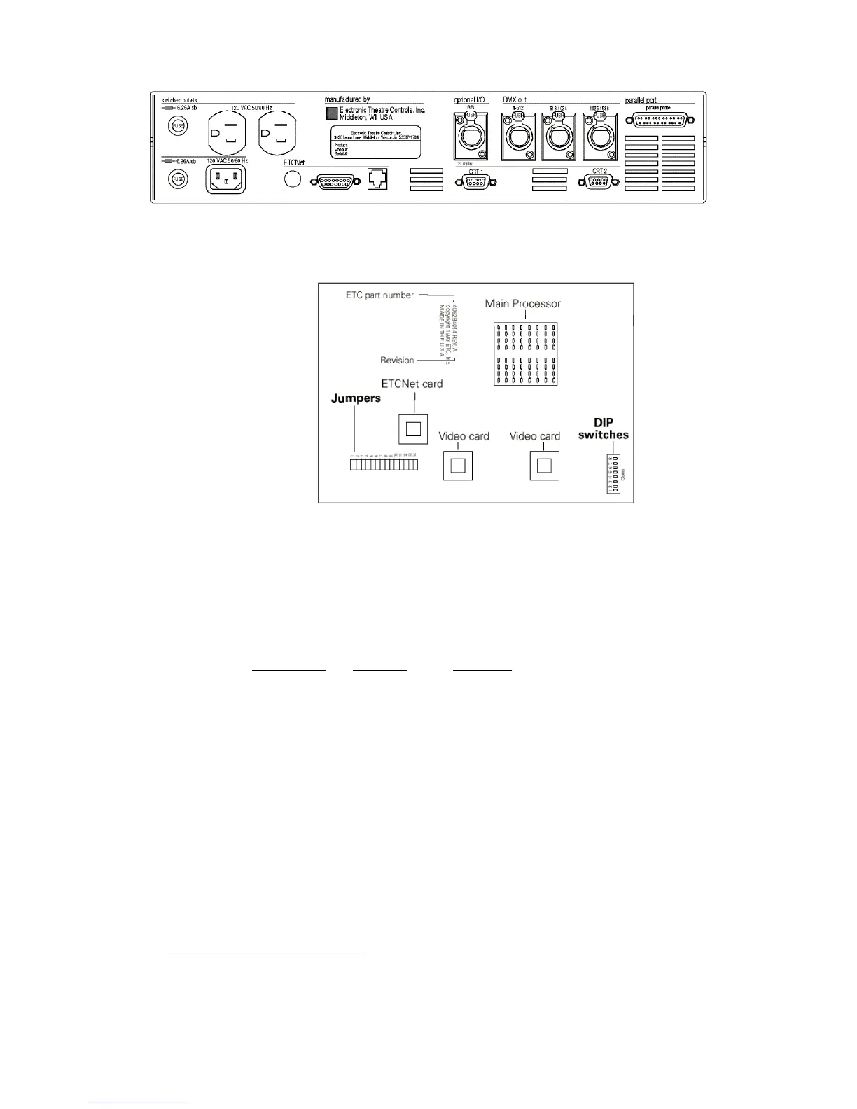
RIU DIP switch and jumper settings
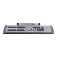
The RIU’s main circuit board contains one 8-switch DIP at location S1 and
a set of 14 jumpers at location J22, as shown in the illustration below.
1. Remove the screws that secure the top panel.
2. Raise the top panel to expose the internal circuitry.
3. Locate the DIP switches at location S1 on the corner of the circuit
board nearest the power switch. Switches are either On (Closed) or
Off (Open). DIP switch 1 must be Off and 2 must be On or the
Remote Interface will not start. Adjust the settings as necessary to
match the following table.
DIP Switch
Position Function
1 Off (Open) Normal operation, Factory Use Only
2 On (Closed) Normal operation, Factory Use Only
3 Off (Open) Normal operation, Factory Use Only
4 Off (Open) Normal operation, Factory Use Only
5 Off (Open) Normal operation, Factory Use Only
6 Off (Open) Normal operation, Factory Use Only
7 Off (Open) Normal operation, Factory Use Only
8 Off (Open) Normal operation, Factory Use Only
4. Locate jumpers 1 through 14. (location J22)
5. Jumper 13 must always be off. Jumper 14 should always be installed.
6. Install jumpers 7 through 12. Be certain jumpers 1 through 6 are not
installed.
124
7. Close the face panel and replace the screws.
8. The Remote Interface checks DIP switch settings when it is turned
on. Restart the unit for new DIP switch settings to take effect.
124.
If using an older console and thinnet wiring, please see Using thinnet with older
consoles, page 334, for different jumper arrangements.