Example: Stack with VIM1-SummitStack Modules
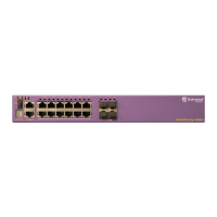
Figure 163 shows an example of a four-switch stack that combines two dierent switch models: two of
each model; four switches in all. For the first switch model, the stacking ports are on installed VIM1-
SummitStack modules. For the second switch model, the stacking ports are on installed SummitStack
stacking modules. The recommended order for connecting the stacking ports is the same as for the
example in Example: Basic Stack with Eight Switches on page 216.
Figure 163: SummitStack Configuration Using Dierent Switch Models and
SummitStack 40G Cables
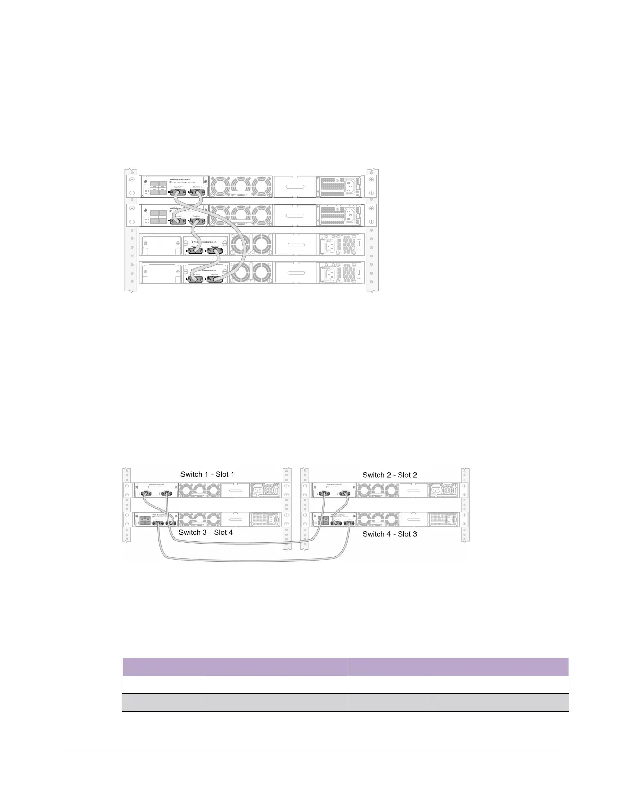
Example: Stacked Switches across Two Racks
The following example shows four switches – two of one model, two of another model – physically
located in two adjacent racks.
Each rack has a switch of one model at the top, with a switch of another model below it. The switches
are connected into a stack using SummitStack ports on installed VIM2-SummitStack and VIM1-
SummitStack modules. In this example, start by connecting the top switches together; they will be
designated the stack master and backup nodes (slot 1 and slot 2, respectively).
Figure 164: SummitStack Connections Using Four Switches with SummitStack Ports
on VIMs
Table 101 lists the recommended order for connecting the stacking ports in this example.
Table 101: Stacked Switches across Two Racks: Connections
Connect this slot and port . . . . . . To this slot and port
Slot 1 Stack Port 2 Slot 2 Stack Port 1
Slot 2 Stack Port 2 Slot 3 Stack Port 1
Building Stacks Connecting the Switches to Form the Stack Ring
ExtremeSwitching Hardware Installation Guide 217
 Loading...
