54200
Users Manual
4-50
∆
U = 0
ÿ
ÿ
V = 0
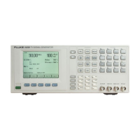
Figure 4-77. DEM 1 (PAL, 625 Line System)
2 rectangles: colored / grey
4 colored squares (PAL coded)
4 colorless squares (anti-PAL coded)
1 grey square
∆
U = 0
ÿ
ÿ
V = 0
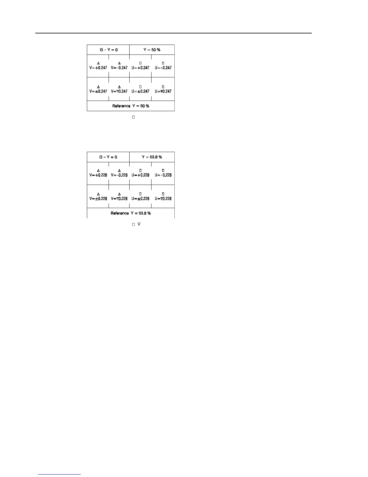
Figure 4-78. DEM 1 (PAL, 525 Line System)
2 rectangles: colored / grey
4 colored squares (PAL coded)
4 colorless squares (anti-PAL coded)
1 grey square
Delay Line Check:
The third bar of this pattern is designed for alignment of the 64
µ
s chrominance delay in
amplitude and phase. 'Venetian blinds' appear when adjustment is needed. It is possible
to distinguish between amplitude and phase faults by noting in which square these blinds
appear. Since the V signal in square one and two are anti-PAL coded, the delay line and
PAL switch should eliminate all R-Y information since this information in successive
lines of the first two squares is subtracted.
When an amplitude error exists between direct and delayed signals, the subtracter output
of the delay line will produce R-Y information in square one and two. The action of the
PAL switch will cause the information to be inverted on alternate lines to give the
venetian blind effect.
When a phase error exists between direct and delayed signals, venetian blinds will show
up in squares three and four. Additionally, they also will appear in the yellowish
horizontal bar (G-Y = 0) of the upper left section of this test pattern.