Remote Control
RS-232 Interface
6
6-11
Interface Functions and Wiring
Operating modes: Communication mode
Baud rates: 110, 150, 300, 600, 1200, 2400, 4800, 9600, 19200
Data bits: 7 or 8
Stop bits: 1 (2 for 110 baud only)
Parity: Odd
Even
None
(with 8 data bits)
Hardware handshake: ON
or OFF
DSR/DTR and CTS/RTS
Hardware connection: 3
wires, no hardware handshake
7
wires, with hardware handshake
Connector: 9-pin D-connector (male)
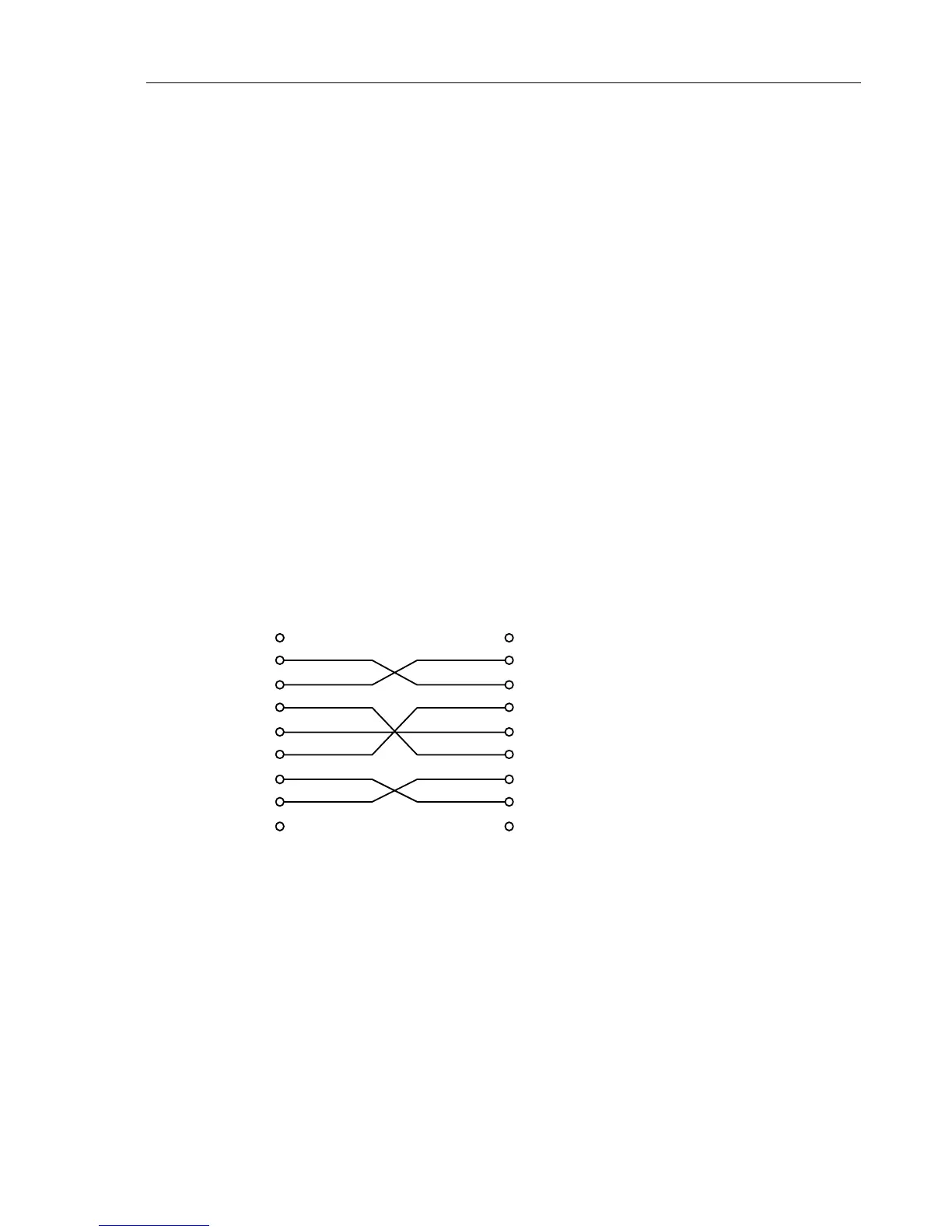
Because the PC and the Fluke 54200 are DTE (Data Terminal Equipment) you should
use the following pin configuration for the RS-232 connection cable. In general it is
recommended that you use a well shielded cable for adequate radio interference
suppression.
to PC
to 54200
9 pin (female) 9 pin (female)
SIGNAL PIN
PIN SIGNAL
1.1
RxD 2 2 RxD Received Data
TxD 3 3 TxD Transmitted Data
DTR 4 4 DTR Data Terminal Ready
GND 5 5 GND Signal Ground
DSR 6 6 DSR Data Set Ready
RTS 7 7 RTS Request To Send
CTS 8 8 CTS Clear To Send
99
This cable can be purchased from your local Fluke organization, order number
PM 9536/041.