54200
Users Manual
4-58
Applications:
The color bar pattern in fact provides sufficient information for a good overall check on
color performance. This includes the checks on burst keying, subcarrier regeneration,
RGB amplifiers, the delay chrominance/luminance and saturation check.
For VCRs this pattern is mainly used for checking the delay chrominance to luminance,
saturation, or to adjust the AFC and balance of the chrominance.
For S-VHS recorders the color bar pattern signal is required as CVBS, RGB, or Y/C
signal. Checks and adjustments of the RGB encoder or decoder, luminance suppression,
and cross luminance suppression of the Y/C separator are realized by this pattern.
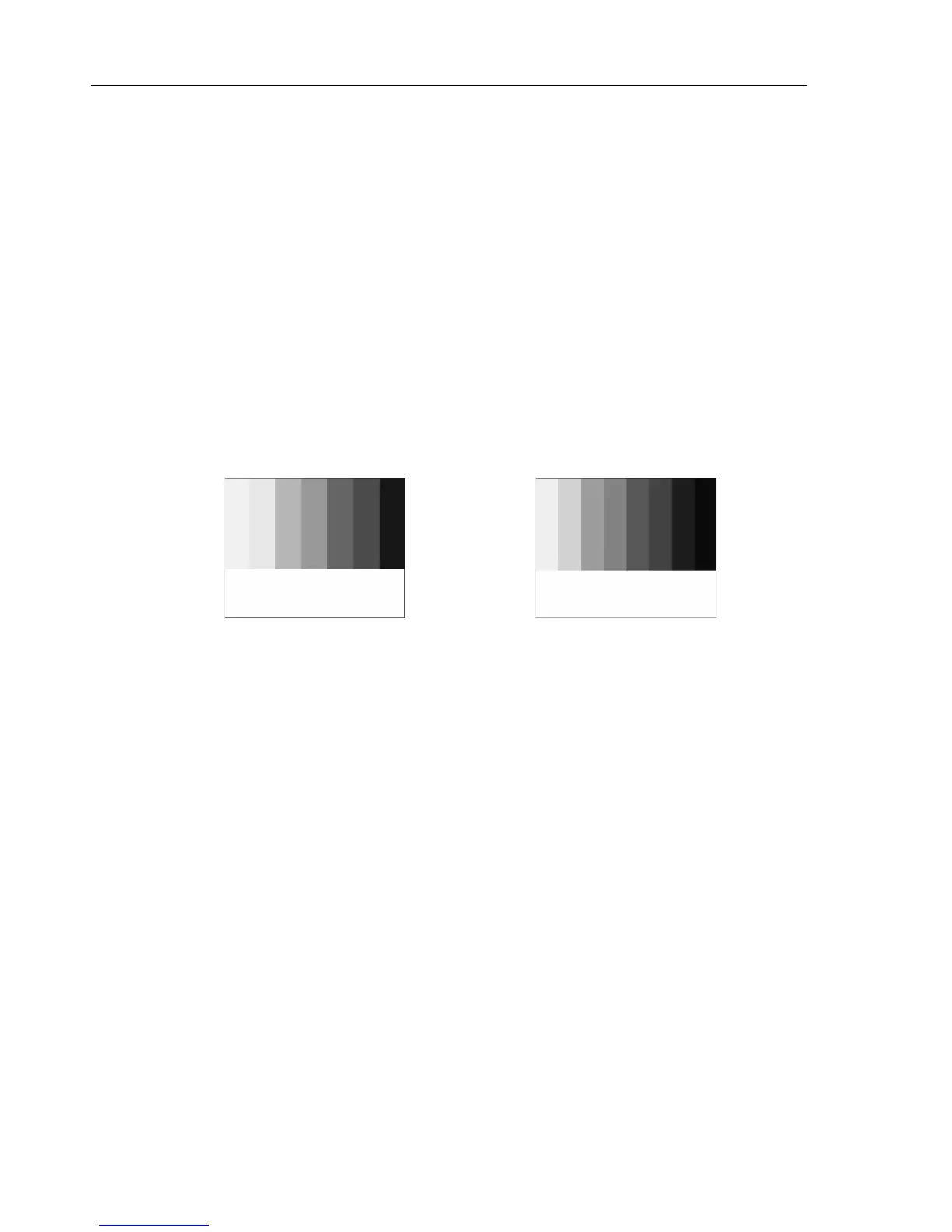
Split Field Color Bar
This pattern comprises 2/3 field of the color bar signal and 1/3 field purity pattern. 75%
or 100% White Level (WL) is selectable. Amplitudes of the remaining bars are
WL/0/75/0 for 625 line systems respectively WL/7.5/75/7.5 for 525 line systems. Any
color of the color bar signal is selectable in the lower third part of the screen. The level
of the purity part is identical to the color bar part. Select the purity-color first followed
by the Split Field Color Bar.
Figure 4-88.Split Field Color Bar, Figure 4-89. Split Field Color Bar,
525 Line Systems 625 Line Systems
Applications:
The white bar, for example, is used as reference to adjust the amplitude of the color
difference signals with respect to the luminance signal on the picture tube. This signal
can be used for aligning the signal amplitude of the demodulators and matrix circuitry, as
the output can be compared with the reference bar. For example, the blue and green guns
(path) can be switched off to allow the amplitude of the R-Y signal to be adjusted. This
is done by ensuring that no difference in brightness is observed between the vertical bars
five and six of the color bar and the horizontal reference bar. In a similar fashion, the
amplitude of the B-Y demodulator can be determined. After this test, the matrix circuit
can be checked with only the green gun switched on. For further applications, see ‘Full
Field Color Bar’ earlier in this chapter.