54200
Users Manual
4-56
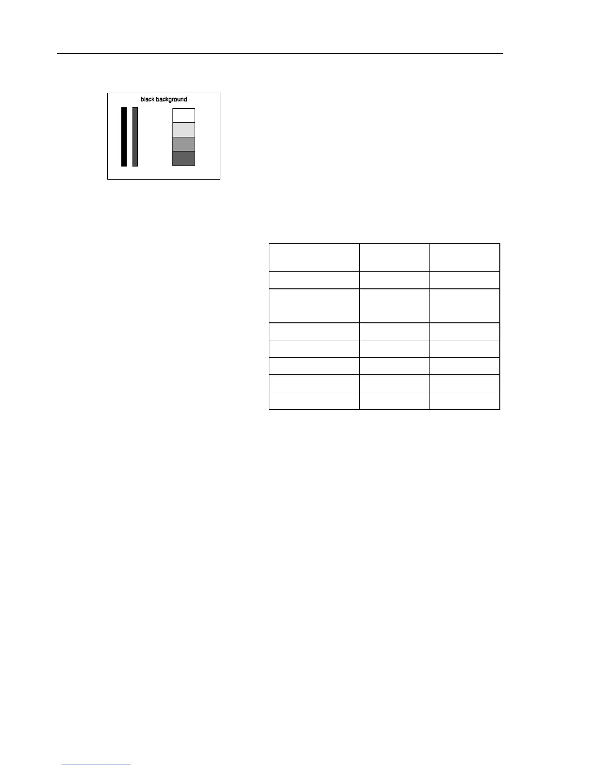
PLUGE
1 2 3
Figure 4-86. PLUGE
Description:
The PLUGE signal (Picture Line-Up Generating
Equipment) is an international standardized B/W test
pattern with color burst according to CCIR Rep. 1221
and comprises three vertical bars on a black
background.
Table 4-5. PLUGE
625
Line System
525
Line System
Background Y = 0% Y = 7.5 IRE
Bar 1: ultra black
Bar 2: dark grey
Y = -1.6%
Y = +1.6%
Y = 4.8 IRE
Y = 10.7 IRE
Bar 3: 4 squares:
white Y = 100% Y = 100 IRE
1st grey Y = 64.3% Y = 67 IRE
2nd grey Y = 28.6% Y = 33.9 IRE
3rd grey Y = 15.7% Y = 22 IRE
Applications:
PLUGE is used to perform accurate and consistent
line-up of picture monitors. The usual procedure is to
adjust the brightness control of a monitor so that bar 1
is invisible on the background while bar 2 can be still
distinguished. The white level luminance is mainly
adjusted by the contrast control to 70
±
10 cd/m
2
by
means of the upper 100% white area of the vertical
greyscale.